DI–720/DI–722/DI–730 Series User Manual
Accessories
46
DI-725(E) Channel Expansion Unit
The DI-725 is a 32-channel analog expansion device for DI-400, DI-720, and DI-730 instruments. The DI-725 fea-
tures 32 differential analog inputs. The DI-725 is powered by the host DI-400, DI-720, or DI-730 instrument and in
most cases will not need an additional power supply. However, when several DI-725s are linked together, an addi-
tional power source may be required (indicated by a glowing POWER LOW lamp). The DI-725E requires an addi-
tional power source connected via the power input jacks located on the rear panel of the instrument.
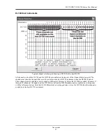
Input signal ranges are as follows:
* For the DI-725, overvoltage protection is ±30V powered on and off.
** For the DI-725E, overvoltage protection is ±120V powered on and off.
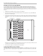
In return for the 32 expansion channels it provides, each DI-725 consumes two channels from its host instrument.
When a single DI-725 is connected to a DI-400, the combination provides 46 total channels (14 channels are still
available on the host DI-400). When connected to a DI-720, the combination delivers 62 total channels (30 are still
available on the host DI-720). When connected to a DI-730, the DI-725 adds 32 high level differential inputs to the
host’s 8 wide measurement range inputs for a diverse blend of 40 total channels. A maximum of 240 channels may be
configured using multiple DI-725s.
Connecting the DI-725 to the Host Instrument
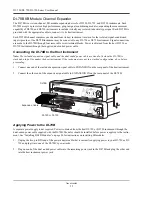
NOTE: The included expansion signal cable and dual-ended power cable are sized to fit when the DI-725 is stacked
on top of (or below) the host DI-720 or DI-730 instrument. If you are using these instruments and they are not in a
stacked configuration, do so before proceeding.
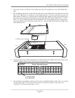
1.
Connect the appropriate end of the included expansion signal cable to the host instrument:
2.
Connect the other end of the expansion cable to EXPANSION IN on the rear panel of the DI-725. Power for the
DI-725 is obtained from the host instrument through this cable. Power for the DI-725E must be supplied via the
power input jacks.
Features, Controls, and Indicators
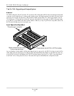
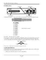
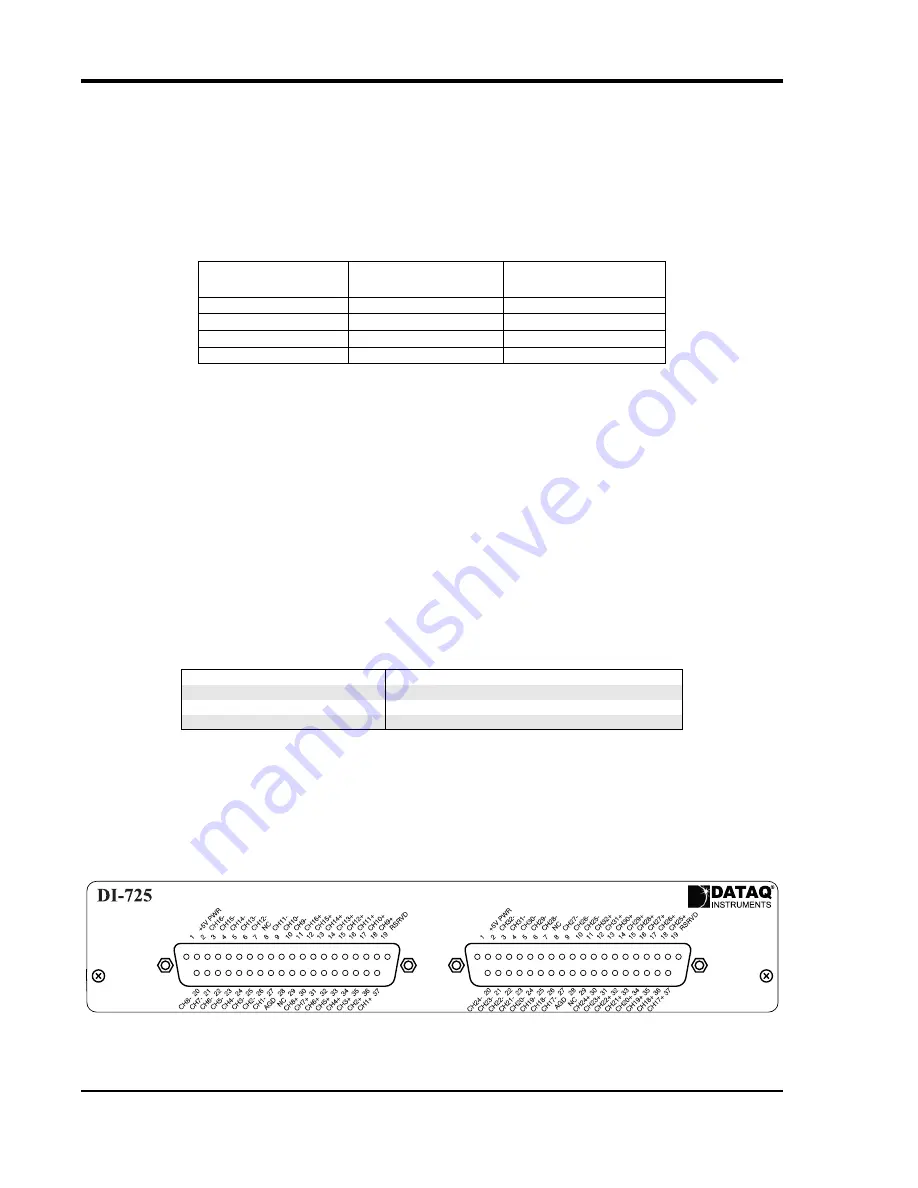
DI-725 Front Panel
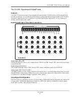
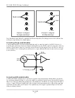
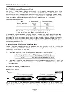
The two, 37-pin, male “D” connectors are used to connect your analog input signals to the DI-725. It can accept 32
high-level or preconditioned analog inputs in a differential configuration (one positive (+) and one negative (-) signal
Gain
(Software Selectable)
Measurement Range
(DI-725*)
Measurement Range
(DI-725E**)
1
±10V
±20V
2
±5V
±10V
4
±2.5V
±5V
8
±1.25V
±2.5V
If you have this instrument:
Then connect the expansion cable to:
DI-400
The DI-400’s 37-pin “D” connector
DI-720
EXPANSION on the rear panel of the DI-720
DI-730
EXPANSION on the rear panel of the DI-730
Summary of Contents for DI-725/E
Page 2: ......
Page 4: ......
Page 6: ......
Page 10: ......
Page 32: ......
Page 40: ......
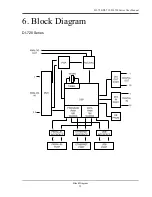
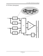
Page 45: ...DI 720 DI 722 DI 730 Series User Manual Block Diagram 35 6 Block Diagram DI 720 Series 1 32...
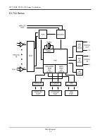
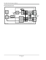
Page 46: ...DI 720 DI 722 DI 730 Series User Manual Block Diagram 36 DI 722 Series...
Page 106: ......
Page 107: ......

