DI–720/DI–722/DI–730 Series User Manual
Accessories
48
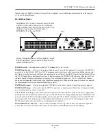
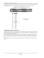
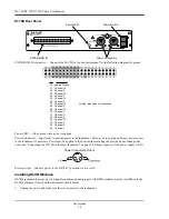
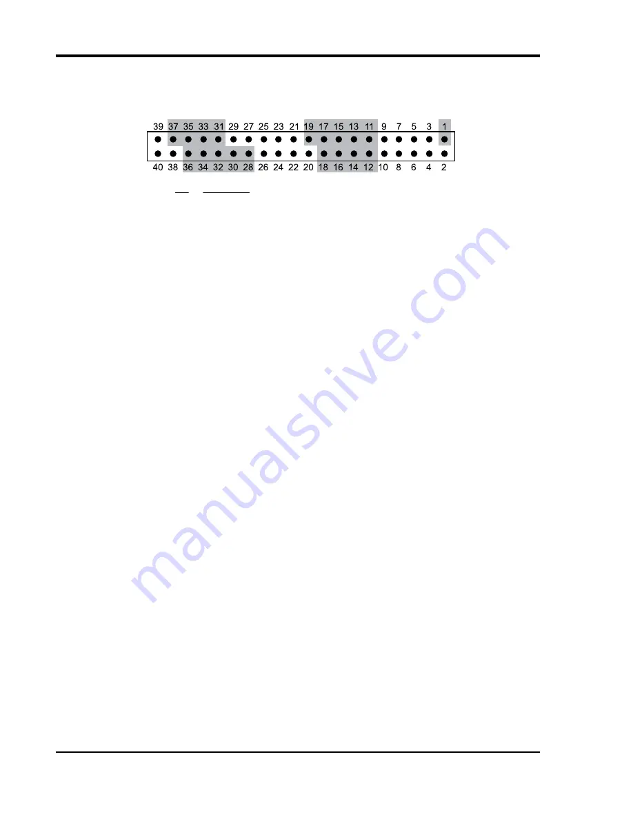
EXPANSION IN connector
— Connects the DI-725 to its host DI-400, DI-720, or DI-730 instrument.
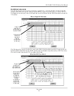
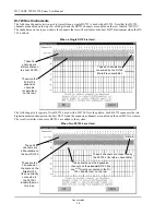
Configuring Channels with the DI-725
In W
IN
D
AQ
/Pro or W
IN
D
AQ
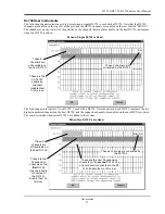
/Pro+ data acquisition software, channels are enabled or configured for acquisition with
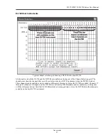
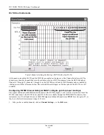
the channel selection grid. The channel selection grid is accessed by selecting Channels… from the Edit menu (in the
SET-UP operating mode of W
IN
D
AQ
software).
Each box in this grid potentially represents an input channel. An input channel is enabled by clicking the desired box.
Which box you click, which mouse button you click with, and how many times you click the mouse button deter-
mines whether the input channel is enabled for single-ended operation, differential operation, or digital input opera-
tion.
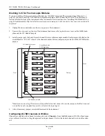
The following pages show how to enable channels when using the DI-725 with a DI-400, DI-720, and DI-730 host
instrument.
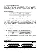
Description
+5V
Ch 16
Ch 15
Ch 14
Ch 13
Ch 12
Ch 11
Ch 10
Ch 9
Analog Gnd
Analog Gnd
Ch 8
Ch 7
Ch 6
Ch 5
Ch 4
Ch 3
Ch 2
Ch 1
Pin
1
11
12
13
14
15
16
17
18
19
28
30
31
32
33
34
35
36
37
All other pins have no
connection.
EXPANSION IN and EXPANSION OUT Pinout
Summary of Contents for DI-725/E
Page 2: ......
Page 4: ......
Page 6: ......
Page 10: ......
Page 32: ......
Page 40: ......
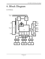
Page 45: ...DI 720 DI 722 DI 730 Series User Manual Block Diagram 35 6 Block Diagram DI 720 Series 1 32...
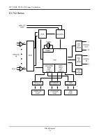
Page 46: ...DI 720 DI 722 DI 730 Series User Manual Block Diagram 36 DI 722 Series...
Page 106: ......
Page 107: ......


