DI–720/DI–722/DI–730 Series User Manual
Accessories
49
DI-400 Host Instruments
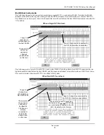
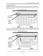
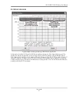
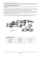
The following channel selection grid is typical when a single DI-725 is used with a DI-400. Note that the DI-400
channels are enabled on the top row of the grid and the DI-725 channels are enabled on the row labeled “MUX A”.
The shaded area on the top row shows the channels that are still available on the host DI-400 instrument when the DI-
725 is added.
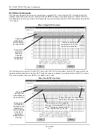
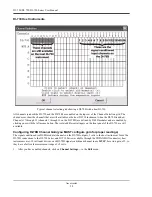
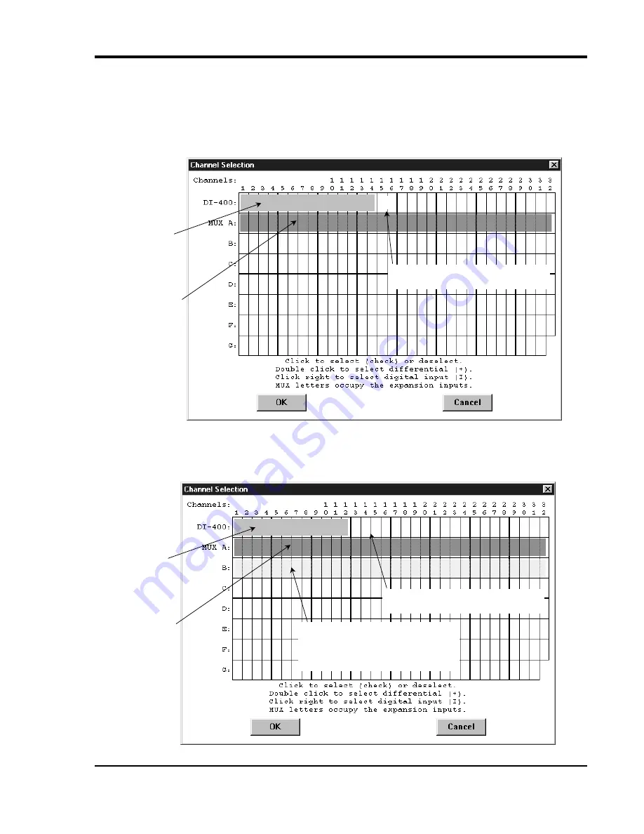
The following grid is typical of two DI-725’s used with a DI-400. Note the pattern. Each DI-725 consumes the two
highest-numbered channels on the host DI-400, and the expansion channels are enabled on the next MUX row down.
The result is similar when more DI-725’s are added to the system.
When a Single DI-725 is Used.
These 14
channels are
still available on
the host DI-400.
A A
These are the
32 DI-725
expansion
channels
(enable them
on this row).
These 2 channels are consumed by
the DI-725 (therefore unavailable).
When Two DI-725’s are Used.
These 12
channels are
still available on
the host DI-400.
A A
These are the
32 expansion
channels on
the
first
DI-
725 (the one
directly
connected to
the DI-400).
Enable them
on this row).
These 4 channels are consumed by
the DI-725’s (therefore unavailable).
B B
These are the next 32 expansion
channels on the
second
DI-725 (the
one
not
directly connected to the DI-
400). Enable them on this row.
Summary of Contents for DI-725/E
Page 2: ......
Page 4: ......
Page 6: ......
Page 10: ......
Page 32: ......
Page 40: ......
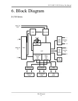
Page 45: ...DI 720 DI 722 DI 730 Series User Manual Block Diagram 35 6 Block Diagram DI 720 Series 1 32...
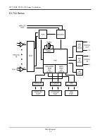
Page 46: ...DI 720 DI 722 DI 730 Series User Manual Block Diagram 36 DI 722 Series...
Page 106: ......
Page 107: ......

