DI–720/DI–722/DI–730 Series User Manual
Accessories
54
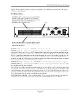
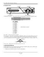
DI-78B Rear Panel
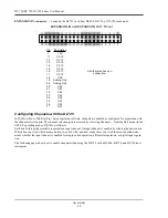
EXPANSION IN connector — Connects the DI-78B to the host instrument. Use the following diagram for pinout.
Power LED — Glows green when power is applied.
Power Connectors — Input jacks to provide power to the instrument. Allows you to apply an alternate power source
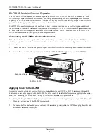
to the instrument, if necessary. Power may be applied to the host instrument using the provided dual-ended power
cable. See “Connecting the DI-78B to the Host Instrument” on page 52. Output capacity of the power supply is 2.5A.
Power switch — Controls power to the DI-78B. 1 position is on, 0 is off.
Installing DI-8B Modules
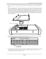
DI-78B instruments accept up to 16 signal conditioned analog inputs. All DI-8B modules must be installed onto the
DI-8B backplane (located on the instrument circuit board).
1.
Unplug the device and make sure there is no power to the instrument.
Power LED
Power Switch
EXPANSION IN
Power Connectors
Description
Analog Ground
Channel 16
Channel 8
Channel 15
Channel 7
Channel 14
Channel 6
Channel 13
Channel 5
Channel 12
Channel 4
Channel 11
Channel 3
Channel 10
Channel 2
Channel 9
Channel 1
Pin
18
21
22
23
24
25
26
27
28
29
30
31
32
33
34
35
36
All other pins have no connection.
Power Connectors Pinout
Summary of Contents for DI-725/E
Page 2: ......
Page 4: ......
Page 6: ......
Page 10: ......
Page 32: ......
Page 40: ......
Page 45: ...DI 720 DI 722 DI 730 Series User Manual Block Diagram 35 6 Block Diagram DI 720 Series 1 32...
Page 46: ...DI 720 DI 722 DI 730 Series User Manual Block Diagram 36 DI 722 Series...
Page 106: ......
Page 107: ......

