DI–720/DI–722/DI–730 Series User Manual
Accessories
63
DI-8B35 Linearized 4-Wire RTD Input Modules
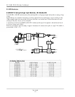
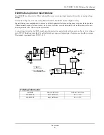
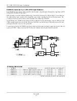
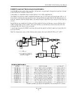
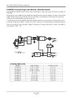
In RTD temperature measurement applications requiring a very high level of accuracy, the DI-8B35 4-Wire RTD
input module offers a significant advantage over 3-wire measurement techniques (see block diagram). The DI-8B35
measures only the voltage dropped across the RTD and almost completely ignores the resistance or length of the RTD
lead wires. The DI-8B34 3-Wire RTD module provides lead resistance compensation, but requires equal lead resis-
tances, while the DI-8B35 does not require matched lead resistances.
Each DI-8B35 module isolates, filters, amplifies, and linearizes a single channel of temperature input from an RTD
and provides an analog voltage output.
RTD excitation is provided from the module using a precision current source. Excitation current does not flow in the
input signal leads, which allows RTD measurements to be made independent of lead resistance. The excitation cur-
rents are small (0.25mA) which minimizes self-heating of the RTD.
Signal filtering is accomplished with a three-pole filter optimized for time and frequency response which provides
70dB of normal-mode-rejection at 60Hz. One pole of this filter is on the field side of the isolation barrier for anti-
aliasing, and the other two are on the system side.
A special input circuit on the DI-8B35 module provides protection against accidental connection of power-line volt-
ages up to 240VAC. Clamp circuits on the I/O and power terminals protect against harmful transients.
Ordering Information
MODEL
INPUT RANGE
OUTPUT RANGE
ACCURACY*
DI-8B35-01
-100°C to +100°C (-148°F to +212°F)
0V to +5V
±0.20°C
DI-8B35-02
0°C to +100°C (+32°F to +212°F)
0V to +5V
±0.15°C
DI-8B35-03
0°C to +200°C (+32°F to +392°F)
0V to +5V
±0.20°C
DI-8B35-04
0°C to +600°C (+32°F to +1112°F)
0V to +5V
±0.45°C
* Includes conformity, hysteresis and repeatability.
Summary of Contents for DI-725/E
Page 2: ......
Page 4: ......
Page 6: ......
Page 10: ......
Page 32: ......
Page 40: ......
Page 45: ...DI 720 DI 722 DI 730 Series User Manual Block Diagram 35 6 Block Diagram DI 720 Series 1 32...
Page 46: ...DI 720 DI 722 DI 730 Series User Manual Block Diagram 36 DI 722 Series...
Page 106: ......
Page 107: ......

