DI–720/DI–722/DI–730 Series User Manual
Table of Contents
viii
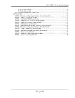
7. Accessories .......................................................................................................................................... 39
The DI-705: Signal Input/Output Option .......................................................................................... 40
General ........................................................................................................................................ 40
Input Signal Configuration .......................................................................................................... 40
The DI-205: Signal Input/Output Panel ............................................................................................. 41
General ........................................................................................................................................ 41
DI-205 Input/Output Panel Interconnections .............................................................................. 41
Input Signal Configuration .......................................................................................................... 41
Connecting a Single-ended Amplifier .................................................................................. 42
Connecting a Differential Amplifier ..................................................................................... 42
DI-725(E) Channel Expansion Unit .................................................................................................. 46
Connecting the DI-725 to the Host Instrument ........................................................................... 46
Features, Controls, and Indicators ............................................................................................... 46
DI-725 Front Panel ............................................................................................................... 46
DI-725 Rear Panel ................................................................................................................ 47
Configuring Channels with the DI-725 ....................................................................................... 48
DI-400 Host Instruments ...................................................................................................... 49
DI-720 Host Instruments ...................................................................................................... 50
DI-730 Host Instruments ...................................................................................................... 51
DI-78B 8B Module Channel Expander ............................................................................................. 52
Connecting the DI-78B to the Host Instrument .......................................................................... 52
Applying Power to the DI-78B ................................................................................................... 52
Features, Controls, and Indicators ............................................................................................... 53
DI-78B Front Panel .............................................................................................................. 53
DI-78B Rear Panel ................................................................................................................ 54
Installing DI-8B Modules ........................................................................................................... 54
Enabling CJC for Thermocouple Modules ................................................................................. 56
Configuring DI-78B Channels in WinDaq ................................................................................. 56
DI-720 Host Instruments ...................................................................................................... 57
DI-730 Host Instruments ...................................................................................................... 58
Configuring DI-78B Channel Gain (you MUST configure gain for proper readings) ......... 58
DI-8B Modules .................................................................................................................................. 60
DI-8B30/31 Analog Voltage Input Modules, 3Hz Bandwidth ................................................... 60
DI-8B32 Analog Current Input Modules .................................................................................... 61
DI-8B34 Linearized 2- or 3-Wire RTD Input Modules .............................................................. 62
DI-8B35 Linearized 4-Wire RTD Input Modules ....................................................................... 63
DI-8B36 Potentiometer Input Modules ....................................................................................... 64
DI-8B38 Strain Gage Input Modules, Narrow & Wide Bandwidth ............................................ 65
DI-8B40/41 Analog Voltage Input Modules, 1kHz Bandwidth ................................................. 66
DI-8B42 2-Wire Transmitter Interface Modules ........................................................................ 67
DI-8B45 Frequency Input Modules ............................................................................................ 68
DI-8B47 Linearized Thermocouple Input Modules .................................................................... 69
DI-8B50/51 Analog Voltage Input Modules, 20kHz Bandwidth ............................................... 70
DI-75B 5B Module Channel Expander ............................................................................................. 71
Connecting the DI-75B to the Host Instrument .......................................................................... 71
Applying Power to the DI-75B ................................................................................................... 71
Features, Controls, and Indicators ............................................................................................... 72
DI-75B Front Panel .............................................................................................................. 72
DI-75B Rear Panel ................................................................................................................ 73
Configuring Channels with the DI-75B ...................................................................................... 74
Summary of Contents for DI-725/E
Page 2: ......
Page 4: ......
Page 6: ......
Page 10: ......
Page 32: ......
Page 40: ......
Page 45: ...DI 720 DI 722 DI 730 Series User Manual Block Diagram 35 6 Block Diagram DI 720 Series 1 32...
Page 46: ...DI 720 DI 722 DI 730 Series User Manual Block Diagram 36 DI 722 Series...
Page 106: ......
Page 107: ......


