DI–720/DI–722/DI–730 Series User Manual
Accessories
74
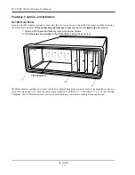
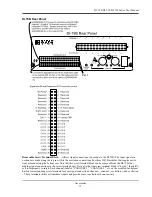
POWER switch
— Controls power to the DI-75B. 1 is on, 0 is off.
POWER input jacks
— Allows you to apply an alternate power source to the instrument, if necessary. When used
with either a DI-720 or DI-730, the DI-75B-7 can be powered by these instruments through the supplied dual-ended
power cable. Simply unplug the five-pin DIN end of the power adapter cable that is currently supplying power to
your DI-720 or DI-730, and plug it into one of the DI-75B's power input jacks. Now plug one end of the dual-ended
power cable into the remaining power jack on the DI-75B and plug the other end into the host instrument power input
jack. When used with a DI-700, the DI-75B-4 requires a separate power supply (user-supplied or available from
Dataq Instruments as an additional cost item, part number 100454-25R).
POWER status lamp
— Glows green when the POWER switch is in the 1 position, indicating power is applied to
the DI-75B.
POWER LOW lamp
— Glows red when the DI-75B cannot derive adequate power from its host instrument. In this
case, an alternate power source is required. Any suitable power source (+9 to +36 volts DC at 3A maximum) may be
connected to either power input jack to provide the necessary power.
EXPANSION OUT connector
— Used to connect multiple DI-75B's together. Connect one end of an expansion
cable to this connector and connect the other end of the cable to EXPANSION IN on the next DI-75B instrument.
EXPANSION IN connector
— Connects the DI-75B to its host instrument.
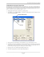
Configuring Channels with the DI-75B
In W
IN
D
AQ
/Pro or W
IN
D
AQ
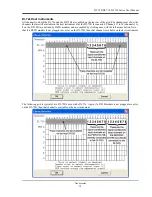
/Pro+ data acquisition software, channels are enabled or configured for acquisition with
the channel selection grid. The channel selection grid is accessed by selecting
Channels…
from the
Edit
menu. Con-
sult the W
IN
D
AQ
help files for more information on selecting channels.
Summary of Contents for DI-725/E
Page 2: ......
Page 4: ......
Page 6: ......
Page 10: ......
Page 32: ......
Page 40: ......
Page 45: ...DI 720 DI 722 DI 730 Series User Manual Block Diagram 35 6 Block Diagram DI 720 Series 1 32...
Page 46: ...DI 720 DI 722 DI 730 Series User Manual Block Diagram 36 DI 722 Series...
Page 106: ......
Page 107: ......

