DI–720/DI–722/DI–730 Series User Manual
Accessories
76
DI-730 Host Instruments
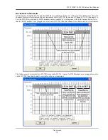
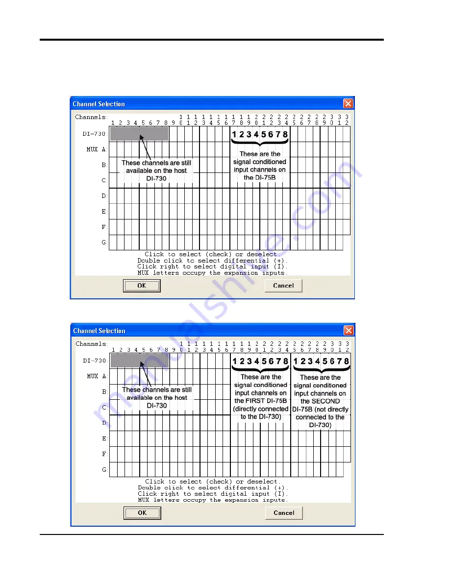
All channels (on both the DI-730 and the DI-75B) are enabled on the top row of the grid. The shaded area shows the
channels still available on the host DI-730 instrument when the DI-75B is connected. Channels 17 to 24 (channels 1
to 8 on the DI-75B) are defined by DI-5B modules and are enabled by clicking once with the left mouse button. Note
that if a DI-5B module is not plugged into a slot on the DI-75B, then that channel is available on the host instrument.
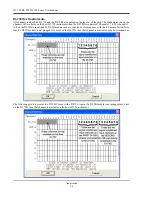
The following grid is typical of two DI-75B' s used with a DI-730. Again, if a DI-5B module is not plugged into a slot
on the DI-75B, then that channel is available on the host DI-730 instrument.
Summary of Contents for DI-725/E
Page 2: ......
Page 4: ......
Page 6: ......
Page 10: ......
Page 32: ......
Page 40: ......
Page 45: ...DI 720 DI 722 DI 730 Series User Manual Block Diagram 35 6 Block Diagram DI 720 Series 1 32...
Page 46: ...DI 720 DI 722 DI 730 Series User Manual Block Diagram 36 DI 722 Series...
Page 106: ......
Page 107: ......

