AP25 Installation and Operating Guide
Page 60
AP25 Installation & Operating Guide
Document # 9301H79500 Ver. 1.00
4.2.6 Version, Serial Number, and MAC address
The upper left corner of the screen displays software version, build date, AP25 serial
number & configuration, and its unique MAC address.
4.2.7 System Monitor
The upper right corner of the screen displays the internal board temperatures, the current
fan speed, and the model code.
The lower portion on the first screen displays board information such as board ID,
Address, hardware revision level, loader version, loader check-sum, firmware version,
and firmware check-sum.
The lower portion on the second screen displays the expected and actual bus voltages for
each board. It is normal for the actual level to vary slightly from the expected. The
background color for the expected and actual values will turn red should the actual
voltage be out of the acceptable range.
4.2.8 More
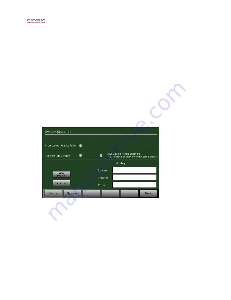
Selecting the More button will access the second System Setup screen
Menu (System) > More
Figure 33. System Setup (2) Screen
4.2.8.1
Monitor-out tracks fader
4.2.8.2
“Expert” Nav Mode
When “Expert” Navigation Mode is enabled, the normal AP25 menu structure is replaced with a
setup screen that provides quick access to the main menu buttons. After enabling, the new
screen appears when the “System” button is pressed. It must be disabled to return to the normal
menu structure. Note: The “Home” screen function is not changed and the unavailable buttons
will be faded out (button availability is related to the input for the currently selected format).


