background image


DN200 User Manual Rel 1.0 

The  wireless  device’s  antenna  sends  a  radio  signal  that  is  polarized  in  a  particular  direction.  The 
antenna’s receive sensitivity is also higher for radio signals that have the same polarization. To maximize 
the performance of the wireless link, both antennas must be set to the same polarization direction.  


1.2.2  Radio Interference 

The avoidance of radio interference is an important part of wireless link planning. Interference is caused 
by other radio transmissions using the same or an adjacent channel frequency. You should first scan your 
proposed  site  using  a  spectrum  analyzer  to  determine  if  there  are  any  strong  radio  signals  using  the 
802.11a/b/g/n  channel  frequencies,  and  find  the  noise  floor.  Always  use  a  channel  frequency  that  is 
furthest away from another signal. 

If  radio  interference  is  still  a  problem  with  your  wireless  link,  changing  the  antenna  polarization 
direction may improve the situation. 


1.2.3  Weather Conditions 

When  planning  wireless  links,  you  must  take  into  account  any  extreme  weather  conditions  that  are 
known to affect the location. Consider these factors: 


Lightning

  —  The  wireless  device  includes  its  own  built-in  lightning  protection  via  chassis 

grounding. However, you should make sure that the unit, any supporting structure, and cables are all 
properly  grounded.  Additional  protection  using  lightning  rods,  lightning  arrestors,  or  surge 
suppressors may also be employed. 


Humidity

  —  The  DN200  is  weatherproofed  against  rain.  However,  it  is  recommended  to  use 

weatherproof boots on cables connecting to the DN200 or to apply weatherproof sealing tape around 
connectors  for  extra  protection.  If  moisture  enters  a  connector,  it  may  cause  degradation  in 
performance or even a complete failure of the link. 


Snow  and  Ice

  —  Falling  snow,  like  rain,  has  no  significant  effect  on  the  radio  signal.  However,  a 

buildup of snow or ice on antennas may cause the link to fail. 


1.3 

Ethernet Cabling 

When  a  suitable  antenna  location  has  been  determined,  you  must  plan  a  cable  route  from  the  DN200 
wireless device outdoors to the equipment indoors.  If a power injector/adapter module is used, it is for 
indoor installation only.  Consider these points: 


The Ethernet cable length should never be longer than 90 m (295 ft) 


Determine a building entry point for the cable 


Determine if conduits, bracing, or other structures are required for safety or protection of the cable 


Consider using lightning protection at the power injector end of the cable. 


1.4 

Grounding 

It is important that the wireless device, cables, and any supporting structures are properly grounded. The 
wireless device unit includes a grounding screw for attaching a ground wire. Be sure that grounding is 
available and that it meets local and national electrical codes. 

Summary of Contents for DN200

Page 1: ...s Point Installation and User Guide Version 1 42 Rev 3 7 Effective Date Jan 2012 Document 4001 Datasat Technologies 5 Tavistock Estate Ruscombe Lane Twyford RG10 9NJ UK Datasat Technologies 9631 Topan...

Page 2: ...NG OUT OF THE USE MISUSE OR INABILITY TO USE THIS PRODUCT OR RELATED DOCUMENTATION INFORMATION TO THE USER The user s manual or instruction manual for an intentional or unintentional radiator shall ca...

Page 3: ...er trademarks are the properties of their respective owners Document No 4001_DN200_Manual_Rev3 7 January 2012 Record of Changes Manual Version Date Description June 2011 Preliminary version August 201...

Page 4: ...ONS 18 1 3 ETHERNET CABLING 18 1 4 GROUNDING 18 1 5 SYSTEM SETUP 19 1 5 1 ACCESSING THE WEB INTERFACE GUI 19 1 5 2 LAN PORT POWER OVER ETHERNET 22 1 6 SYSTEM CONFIGURATION 22 1 7 NAT FIREWALL 23 1 8 M...

Page 5: ...WITH THE INTERNAL POE ENABLED 35 1 17 3 WIRING AN EXTERNAL SUPPLY 36 1 18 CONNECTING THE OPTIONAL EXTERNAL POWER INJECTOR 9004H49000 36 1 19 ANTENNA ALIGNMENT 37 1 19 1 VIBRATION CERTIFICATION 39 2 0...

Page 6: ...by skilled network planners The DN200 is a stand alone device that provides the following capabilities Dual Band Wireless Access Point 802 11a b g n with support for wireless access over 5 GHz or 2 4...

Page 7: ...sat Technologies prior to shipping any parts or merchandise to receive a Return Merchandise Authorization number Datasat Technologies s shipping address is Datasat Technologies Attn RMA 9631 Topanga C...

Page 8: ...strictions You may not i copy distribute sublicense lease transfer or use for external purposes the Software ii reverse engineer decompile disassemble translate modify attempt to reveal the source cod...

Page 9: ...BOVE LIMITATION OR EXCLUSION MAY NOT APPLY TO YOU 7 General This License shall be governed by the laws of the State of California as applied to contracts performed wholly therein In any action brought...

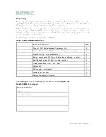
Page 10: ...ctory Use the packing slip that came with your unit to verify received inventory The following is a standard packing list for the DN200 Table 1 DN200 Standard Packing Kit ITEM DESCRIPTION QTY Wing nut...

Page 11: ...point to multipoint see table 1 1 2 The DN200 Radio does not support DFS Radar avoidance in this band This band is not available for equipment supplied to FCC regulatory regions For DFS support kindly...

Page 12: ...mum Power from Intentional Radiator Maximum Antenna Gain dBi EIRP dBm 30dBm or 1 Watt 6 36 27dBm or 500mW 15 42 24dBm or 250mW 24 48 22dBm or 160mW 30 52 NOTE The FCC Terminology of Intentional Radiat...

Page 13: ...IT IS HIGHLY ADVISED THAT A PROFESSIONAL FREQUENCY MANAGEMENT PLAN IS IMPLEMENTED TO ENSURE MAXIMUM SPECTRAL EFFICIENCY DATASAT TECHNOLOGIES CAN PROVIDE SUCH A PLAN IF REQUIRED 1 1 3 Sample Point To...

Page 14: ...a specific throughput and bit error rate The threshold at the higher throughput levels achievable in 802 11n systems is significantly higher than required for 11 Mb sec Noise is also a consideration w...

Page 15: ...een the antennas or near the direct path path loss exponent 2 r 3 NLOS Non line of sight direct path is partially obstructed creating weak multipath Path loss exponent 3 r 4 NLOS Non line of sight pat...

Page 16: ...t involves the area along a link through which the bulk of the radio signal power travels This area is known as the first Fresnel Zone of the radio link For a radio link no object including the ground...

Page 17: ...ain the minimum required clearance Use the following table to estimate the required minimum clearance above the ground or path obstruction for 5 GHz links 1 2 1 Antenna Position and Polarization Once...

Page 18: ...ucture and cables are all properly grounded Additional protection using lightning rods lightning arrestors or surge suppressors may also be employed Humidity The DN200 is weatherproofed against rain H...

Page 19: ...e the DN200 via Ethernet 1 follow the steps below Make sure the DN200 in not powered up Always make sure all power connections are complete before powering the DN200 This is specially true when using...

Page 20: ...low If Ethernet settings have been changed click on Save The confirmation screen will be displayed Now click on Home and then click Reboot The unit takes about 60 secs to reboot Make sure your Laptop...

Page 21: ...c mode need to run the same mode and configurations Wireless Channel Select the appropriate wireless channel The channels displayed are inline with the local regulatory laws If a channel intended for...

Page 22: ...supply through the DC IN port ONLY A maximum output of 15W at 48V can be supplied per PoE port Please make sure good quality CAT 5 or higher cable is used This configuration uses NON STANDARD PoE impl...

Page 23: ...DN200 User Manual Rel 1 0 1 7 NAT Firewall...

Page 24: ...ws a typical multicast configuration Example To enable multicast flows from 192 168 1 92 attached on the wired segment eth0 IGMP multimedia server to all wireless ra_ap0 clients who are recipients ins...

Page 25: ...le to assign dynamic addresses based on those subnets The DHCP server shall assign a common DNS server to all the clients within the block The DHCP server shall be aware of the access point IP address...

Page 26: ...l 1 0 In the example above DHCP server running on 192 168 1 71 serves addresses to all clients associating to the AP If the DN200 is an MPP example below the MPP allocates addresses to clients attachi...

Page 27: ...DN200 User Manual Rel 1 0...

Page 28: ...option broadcast address 10 150 5 255 subnet 10 151 5 0 netmask 255 255 255 0 range 10 151 5 60 10 151 5 200 option broadcast address 10 151 5 255 subnet 10 140 5 0 netmask 255 255 255 0 range 10 140...

Page 29: ...r Ethernet cable of required length or a cable meeting the pin out configuration specification to the required length not to exceed 90 meters total shielded CAT 5 Ethernet 8 pin DIN to RJ 45 Power sup...

Page 30: ...n 1 and 2 5 inches in diameter Figure 1 Pole Mounting Hardware Perform the following steps to mount the DN200 to a pole 1 Thread carriage bolts through square holes of those clamp pieces which also ha...

Page 31: ...igure 2 Clamp Placement on the DN200 3 Screw the clamp to the DN200 using a socket cap screw Use a lock washer under the screw head and then a flat washer against the clamp The provided hex key may be...

Page 32: ...roduct and where possible use a 2x2 MIMO antenna For MIMO to effectively work complete isolation needs to be provided between the two radio streams You may use a single dual polarized antenna or multi...

Page 33: ...per second 5 kHz 5 000 000 cycles per second 5 MHz 5 000 000 000 cycles per second 5 GHz We know that radio waves travel at the speed of light 186 000 miles per sec or 3 x 10⁸ meters per sec and we ca...

Page 34: ...of power while a 3dB loss represents 1 2 of the power 1 15 Connect a Grounding Wire to the DN200 Provide Earth ground to the DN200 wing nut stud Use a wire gauge and color that complies with local ele...

Page 35: ...prior to crimping on the RJ45 connector Alternatively apply weatherproofing tape not included around the Ethernet connector Tape is a less desirable solution 1 17 Connect the External DC Power The DN...

Page 36: ...is important to make sure that the red O ring is inserted This assures a weather resistant connection between the plug on the cable and the jack on the DN200 1 18 Connecting the Optional External Powe...

Page 37: ...each end of the link The use of cell phones or two way radio communication may help with coordination To start you can just point the antennas at each other using binoculars or a compass to set the g...

Page 38: ...DN200 User Manual Rel 1 0...

Page 39: ...DN200 User Manual Rel 1 0 1 19 1 Vibration Certification...

Page 40: ...ucture 2 3 Power Over Ethernet The DN200 Outdoor Wireless Access Point router supports Power Over Ethernet POE and can be used to power up to two PoE devices as long as power restrictions are met 2 4...

Page 41: ...ty of the final customer installer to make sure that link budgets are in line with local rules and regulations and the radio installed does not violate local regulatory laws ANTENNA TYPES 2 4GHz SNo A...

Page 42: ...Type Omni directional Frequency 4 9 5 875GHz Gain 10dBi Polarization Vertical Connector N Type Coverage H 360 E 10 2 DT OM360I 5805 RPTNC Type Omni directional Frequency 5 1 5 875GHz Gain 5dBi Polari...

Page 43: ...GHz Antenna types 1 DT ST120O 5805 N Type Sector Frequency 2 4 5 1 5 8GHz Gain 2x5dBi Polarization Vertical and Dual Slant Connector N Type Coverage 5GHz H 120 E 70 2 4GHz H 120 E 70 2 DT ST060O 5875...

Reviews: