background image

52

   SH4 BASE-STANDARD

CHAPTER 8

PERIODICAL CHECKS

The following is a list of recommended check and maintenance operations that should

be periodically carried-out by qualified personnel (see "

Controls after first installation" on

page 20

).

Check that:

• The ESPE remains in Safe State (Red OSSD LED ON) during beam interruption along 

The ESPE stays in SAFE state during beam interruption along the entire protected 

area, using the specific Test Piece (TP-14 or TP-30)

• The ESPE is correctly aligned. Press slightly product side, in both directions and the 

red LED (named OSSD on RX side) must not turn ON.

• Enabling the TEST function (on TX side), the OSSD outputs should open (the red 

LED, OSSD on RX side, is ON and the controlled machine stops)

• The response time upon machine STOP (including response time of the ESPE and 

of the machine) is within the limits defined for the calculation of the safety dis

-

tance (see "

Installation" on page 6

).

• The safety distance between the dangerous areas and the ESPE are in accordance 

with the instructions included in "

Installation" on page 6

.

• Access of a person between ESPE and machine dangerous parts is not possible, 

nor it is possible for him/her to stay there

• Access to the dangerous area of the machine from any unprotected area is not 

possible

• The ESPE and the external electrical connections are not damaged.

The frequency of checks depends on the particular application and on the operating

conditions of the safety light curtain.

Summary of Contents for SH4 BASE-STANDARD

Page 1: ...SH4 BASE STANDARD PRODUCT REFERENCE GUIDE Safety Light Curtains...

Page 2: ...d in this documentation and shall ensure that all notices appear on any reproductions of the documentation Electronic versions of this document may be downloaded from the Datasensing website www datas...

Page 3: ...point protection on drilling machines 12 Example 2 Bending presses 12 Example 3 Paper cutting machines 13 Example 4 Milling machines 13 Safety information 14 General information on device positioning...

Page 4: ...Product disposal 54 APPENDIX A TECHNICAL DATA 55 APPENDIX B AVAILABLE MODELS AND RESPONSE TIMES 58 Models 58 Pairing table 59 Response Times 59 SH4 14 XXXX X X models 59 SH4 30 XXXX X X models 59 SH4...

Page 5: ...s Transmitter main connector 76 Cascade cables 5 poles M12 male female 76 Safety Units 78 Safety unit 78 EDM relay box 78 Couple arms 79 SH T ARMS 79 SH L ARMS 79 Connection Box 80 APPENDIX F CASCADE...

Page 6: ...CONTENTS vi SH4 BASE STANDARD...

Page 7: ...observed when using the laser marker TECHNICAL SUPPORT Support Through the Website Datasensing provides several services as well as technical support through its website Log on to www datasensing com...

Page 8: ...hole unit consumable items 7 use of counterfeit or replacement parts that are neither manufactured nor approved by Datasensing for use in Datasensing manufactured Products 8 any damage or malfunctioni...

Page 9: ...cular requirements for equipment using active optoelectronic pro tective devices EN ISO 13849 1 2015 Safety of machinery Safety related parts of control systems Part 1 General principles for design EN...

Page 10: ...if correctly connected to the OSSD The SH4 safety light curtains are used in all automation fields where it is necessary to control and protect the access to dangerous zones In particular they are use...

Page 11: ...BASE STANDARD STANDARD MUTING ADVANCED FUNCTION Automatic Restart Manual Automatic Restart Reset External Device Monitoring EDM Alignment Function 2 signals T Muting L Muting Single Override 2 signals...

Page 12: ...an Declaration of Con formity is available at www datasensing com Select the link from the downloads sec tion of the product page UKCA Declaration of Conformity Hereby Datasensing S r l declares that...

Page 13: ...COMPLIANCE PRODUCT REFERENCE GUIDE 5...

Page 14: ...tains the following objects Receiver RX Emitter TX Quick Guide of safety light curtain Periodical checklist and maintenance schedule 4 angled fixing brackets and specific fasteners 2 additional angled...

Page 15: ...he ESPE must not be installed close to strong and or flashing light sources in par ticular close to the front window of receiving unit The presence of intense electromagnetic disturbances could affect...

Page 16: ...ction zone and to actuate the sensing device The resolution is related to the part of the body to be protected As shown in the following figure the resolution only depends on the geometrical charac te...

Page 17: ...he figure above the protected height is reported in the table here below MODEL PROTECTED HEIGHT mm SH4 14 30 0300 X X 300 SH4 14 30 0450 X X 450 SH4 14 30 0600 X X 600 SH4 14 30 0750 X X 750 SH4 14 30...

Page 18: ...itioning The following formula is used for the calculation of the safety distance S K t1 t2 C where S Minimum safety distance in mm K Speed of the object limb or body approaching the dangerous area in...

Page 19: ...al examples Let s suppose to have a light curtain with height 600 mm To calculate the distance of the device from the ESPE in a vertical position the follow ing formula is used S K T C where S Minimum...

Page 20: ...ntees installation flexibility for machine dimensions Example 2 Bending presses The safety device must protect the operator from being squashed between the top and bottom tool or the machined part dur...

Page 21: ...reduced profile and the two side slots ensure installation flexibility for machine dimensions Example 4 Milling machines A milling machine is a machine tool used for the shaping of metals and other so...

Page 22: ...fety light curtain must be securely placed in a particular position so that access to the dangerous zone is not possible without the interruption of the beams refer to Installation on page 6 The perso...

Page 23: ...e to install safety light curtain very near to the dangerous zone a second light curtain must be mounted in a horizontal position in order to prevent any lateral access as shown in the following figur...

Page 24: ...ortant to position the safety light curtain according to the minimum distance from reflecting surfaces The minimum distance depends on operating distance between emitter TX and receiver RX real apertu...

Page 25: ...inimum Ddo distance depends on the operating distance between emitter TXA and receiver RXA the effective aperture angle of the ESPE EAA Figure 12 ESPE Type 4 The formula to get Ddo is the following Dd...

Page 26: ...igure provides two examples Figure 13 Recommended positioning for homologous devices CAUTION If two light curtains have to be mounted near each other as reported in the first example of the figure abo...

Page 27: ...ect to the beams Figure 15 Use of deviating mirrors The operator must respect the following precautions when using the deviating mirrors The alignment of the emitter and the receiver can be a very cri...

Page 28: ...LED OSSD on RX side ON and controlled machine stop The response time at machine STOP including the ESPE and machine response times must be included in the limits defined in the calculation of the saf...

Page 29: ...GENERAL INFORMATION ON DEVICE POSITIONING PRODUCT REFERENCE GUIDE 21...

Page 30: ...ed within the operating range of the model used see appendix Technical Data The two units must be positioned the most aligned and parallel possible The next step is the fine alignment as shown in the...

Page 31: ...the bracket against the profile by tightening the M5 hexagonal nuts 3 4 It s possi ble to slide the bracket group along their dedicated rail and fix it once again just working on the above mentioned...

Page 32: ...4 0900 x x SH4 30 0900 x x 909 509 200 SH4 14 1050 x x SH4 30 1050 x x 1059 609 225 SH4 14 1200 x x SH4 30 1200 x x 1209 909 150 454 5 SH4 14 1350 x x SH4 30 1350 x x 1359 1009 175 504 5 SH4 14 1500 x...

Page 33: ...PRODUCT REFERENCE GUIDE 25...

Page 34: ...BASE STANDARD CHAPTER 4 ELECTRICAL CONNECTIONS PIN OUT AND CONFIGURATION PIN CONNECTION All electrical connections to the emitting and receiving units are made through M12 connector s Figure 1 Connec...

Page 35: ...ITTER RX M12 MALE 5 PIN RX M12 MALE 8 PIN TX M12 MALE 5 PIN 1 24V brown 1 RESET RESTART white 1 24V brown 2 OSSD1 white 2 24V brown 2 TEST white 3 0V blue 3 EDM SEL green 3 0V blue 4 OSSD2 black 4 EDM...

Page 36: ...matic Restart mode left side and Manual Restart with monitoring right side Do not use varistors RC circuits or LEDs in parallel at relay inputs or in series at OSSD outputs The OSSD1 and OSSD2 safety...

Page 37: ...e that the light curtain has to control Figure 3 OSSDs connection Figure 4 Behavior of OSSDs OSSD1 OSSD2 OSSD1 OSSD2 OSSD1 OSSD2 OSSD2 OSSD1 24Vdc 24Vdc control by pA control by pB control by pA contr...

Page 38: ...ELECTRICAL CONNECTIONS 30 SH4 BASE STANDARD...

Page 39: ...versa due to dust or vibration The alignment is perfect if the optic axes of the first and the last emitting unit s beams coincide with the optic axes of the corresponding elements of the receiving un...

Page 40: ...a good state of alignment is reached a power OFF and a power ON operation carry back the ESPE in normal operation In Alignment Mode ESPE is always in Safe State and the OSSDs are kept OFF The state of...

Page 41: ...vel is visualized on LED user interface LED meanings Table 1 User interface display in alignment mode INDICATION LED CONFIGURATION Not aligned Not aligned Only first sync aligned Not aligned Only last...

Page 42: ...eaker beam analog level 2 5V ON Medium Signal Level weaker beam analog level 3V ON Maximum Signal Level weaker beam analog level 3V ON NOTE On SH4 light curtains each optical module but the first 15 c...

Page 43: ...interface LED meanings Table 4 User interface display in alignment mode body INDICATION LED CONFIGURATION Not aligned Not aligned Only first sync aligned Not aligned Only last sync aligned LED user in...

Page 44: ...of the light curtain is the safe detection when any object with dimensions equal or greater than the light curtain resolution is placed anywhere within the detection zone the light curtain will detect...

Page 45: ...t is detected the ESPE enters in OFF state Then after the object has been removed from the controlled area the ESPE returns in ON state The response time is the time between the object introduction in...

Page 46: ...s so this time can be any between 0 5 s and 5 s In the timing diagram above the object is already removed Configuration of Restart mode The configuration of Restart mode is done by connecting the MAN...

Page 47: ...on connected to RESET input pin 1 has to be kept pressed for at least 5 seconds in non critical failure state For all critical failure a power cycle is necessary Figure 7 Reset function timing If the...

Page 48: ...cause OSSDs and the effect EDM with the maximum permissible delay Figure 9 EDM function timing Tc 350 ms time between OSSD OFF ON transition and EDM test T0 100 ms time between OSSD ON OFF transition...

Page 49: ...0 5s plus a cycle time and after the response time of the light curtain Figure 10 OSSDs timing for test on TX NOTE On Body models only TEST input may be used to set Emission Range Refer to the next pa...

Page 50: ...ission Range Change Request timings 0 5s after rising edge on TEST input emission is disabled 2s after rising edge on TEST input Range Change Request is activated and both S and L led are lit on user...

Page 51: ...ate of the light curtain for alignment mode normal operation and for troubleshooting activity For each optical module on both RX and TX unit an RGB led will inform about single module status and light...

Page 52: ...e signal status from 2nd module Good Signal on modules no optics intercepted Low Signal on modules no optics intercepted At least one optic intercepted on modules with blinking red light eg Modules wi...

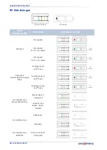
Page 53: ...on OSSD ON Minimum Signal Level Good Signal Level Maximum Signal Level Failure Lockout Power Supply Failure F11 OSSDs failure F22 Microprocessor Failure F33 Optics Failure EDM Failure Restart Failure...

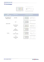
Page 54: ...6 SH4 BASE STANDARD TX Side dialogue ESPE WORKING MODE INDICATION LED CONFIGURATION Normal Operation Emission Active NO CODE Test Emission OFF Test Failure F1 Failure on microprocessor F2 Failure on o...

Page 55: ...alignment mode normal operation and for troubleshooting activity For each optical module on both RX and TX unit an RGB led will inform about single module status and light curtain operation Figure 4...

Page 56: ...nment Normal Operation Single Optic No Signal Level on Nth optic Low Signal Level on Nth optic Good Signal Level on Nth optic Normal Operation Manual Restart Only Manual Restart configured Interlock f...

Page 57: ...SH4 X XXXX X X MODELS PRODUCT REFERENCE GUIDE 49 Failure Lockout Power Supply Failure FER OSSDs failure F1 Microprocessor Failure F2 Optics Failure FE EDM Failure FR Reset Restart Failure...

Page 58: ...STANDARD TX Side dialogue ESPE WORKING MODE INDICATION LED CONFIGURATION Normal Operation Emission Active NO CODE Emission OFF Test Range Change Request Failure F1 Failure on microprocessor F2 Failure...

Page 59: ...SH4 X XXXX X X MODELS PRODUCT REFERENCE GUIDE 51...

Page 60: ...de the OSSD outputs should open the red LED OSSD on RX side is ON and the controlled machine stops The response time upon machine STOP including response time of the ESPE and of the machine is within...

Page 61: ...sensing is at your disposal to carry out the installation The device uses fuses that are not self resetting Consequently in presence of short cir cuits causing the cut off of these fuses both safety l...

Page 62: ...pply too much pressure on the surface in order to avoid making it opaque Please do not use on plastic surfaces or on light curtain painted surfaces alcohol or solvents wool or synthetic cloths paper o...

Page 63: ...4 Vdc 20 a Emitter consumption TX 3 5 W max Receiver consumption RX 5 5 W max without load Outputs 2 OSSDs Outputs for all models 2 Auxiliary Outputs for SH4 XX XXXX A X X models only 1 Lamp Output fo...

Page 64: ...for 14 mm res 0 2 to 20 m for 30 mm res 0 5 to 15 m for body SHORT range 5 to 70 m for body LONG range EAA angle 2 5 at 3 meters Ambient light rejection EN 61496 2 2020 MECHANICAL AND ENVIRONMENTAL DA...

Page 65: ...PRODUCT REFERENCE GUIDE 57...

Page 66: ...027 2100 SH4 14 2250 B 5 957920014 SH4 14 2250 S 8 957920028 2250 SH4 30 0300 B 5 957920057 SH4 30 0300 S 8 957920071 30 mm HAND PROTECTION 300 SH4 30 0450 B 5 957920058 SH4 30 0450 S 8 957920072 450...

Page 67: ...T 5 SH4 2 3 4 XXXX S 8 SH4 2 3 4 XXXX S R 8 SH4 2 3 4 XXXX T 5 MODEL PROTECTED HEIGHT mm NO BEAMS RESPONSETIME ms AIC DISABLE RESPONSETIME ms AIC ENABLE SH4 14 0300 x x 300 30 9 14 SH4 14 0450 x x 45...

Page 68: ...0 72 14 27 SH4 30 1950 x x 1950 78 15 28 SH4 30 2100 x x 2100 84 16 30 SH4 30 2250 x x 2250 90 17 32 MODEL CONTROLLED HEIGHT mm NO BEAMS RESPONSETIME ms AIC DISABLE RESPONSETIME ms AIC ENABLE MODEL CO...

Page 69: ...RESPONSE TIMES PRODUCT REFERENCE GUIDE 61...

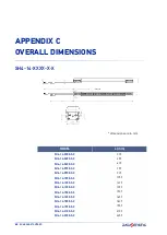
Page 70: ...309 SH4 14 0450 X X 459 SH4 14 0600 X X 609 SH4 14 0750 X X 759 SH4 14 0900 X X 909 SH4 14 1050 X X 1059 SH4 14 1200 X X 1209 SH4 14 1350 X X 1359 SH4 14 1500 X X 1509 SH4 14 1650 X X 1659 SH4 14 1800...

Page 71: ...SH4 30 0450 X X 459 SH4 30 0600 X X 609 SH4 30 0750 X X 759 SH4 30 0900 X X 909 SH4 30 1050 X X 1059 SH4 30 1200 X X 1209 SH4 30 1350 X X 1359 SH4 30 1500 X X 1509 SH4 30 1650 X X 1659 SH4 30 1800 X X...

Page 72: ...OVERALL DIMENSIONS 64 SH4 BASE STANDARD SH4 2 3 4 XXXX X X dimensions are in mm MODEL L mm SH4 2 0500 X X 674 SH4 3 0800 X X 974 SH4 4 0900 X X 1074 SH4 4 1200 X X 1374...

Page 73: ...SH4 2 3 4 XXXX X X PRODUCT REFERENCE GUIDE 65...

Page 74: ...66 SH4 BASE STANDARD APPENDIX D INCLUDED ACCESSORIES METAL ANGLED FIXING BRACKET Figure 5 Metal Angled fixing Bracket NOTE Dimensions are in mm...

Page 75: ...METAL ANGLED FIXING BRACKET PRODUCT REFERENCE GUIDE 67...

Page 76: ...68 SH4 BASE STANDARD APPENDIX E ACCESSORIES BRACKETS Metal Angled Fixing Bracket Figure 6 ST KSTD MODEL DESCRIPTION CODE ST KSTD Angled fixing bracket 4 pcs kit 95ACC1670 NOTE Dimensions are in mm...

Page 77: ...support Figure 9 Angled fixing bracket Anti vibration support Figure 10 Angled fixing bracket Orientable support Anti vibration support MODEL DESCRIPTION CODE ST K4OR Orientable supports 4 pcs kit 95A...

Page 78: ...ACCESSORIES 70 SH4 BASE STANDARD Rotating Bracket Figure 11 ST K4ROT SH MODEL DESCRIPTION CODE ST K4ROT SH Metal top bottom rotating fixing brackes kit 4 brackets for SH4 NOTE Dimensions are in mm...

Page 79: ...e stand H 600 mm 600 95ASE2240 SG PSB 1000 Protective stand H 1000 mm 1000 95ASE2250 SG PSB 1200 Protective stand H 1200 mm 1200 95ASE2260 SG PSB 1650 Protective stand H 1650 mm 1650 95ASE2270 SG PSB...

Page 80: ...ANDARD Plate Kit for Protective Stands Figure 14 Plate kit Mounting with SG P SB Figure 15 Mounting with SG P SB MODEL DESCRIPTION CODE SG P Plate kit with springs 95ASE2290 NOTE Dimensions are in mm...

Page 81: ...X mm CODE SE S 800 Column and floor stand H 800 mm 800 30x30 95ACC1730 SE S 1000 Column and floor stand H 1000 mm 1000 30x30 95ACC1740 SE S 1200 Column and floor stand H 1200 mm 1200 30x30 95ACC1750 S...

Page 82: ...rsion 900 mm 845 676 880 95ASE1690 SG DM 1200 Deviating mirror version 1200 mm 1145 976 1180 95ASE1700 SG DM 1650 Deviating mirror version 1650 mm 1595 1426 1630 95ASE1710 SG DM 1900 Deviating mirror...

Page 83: ...ng kit SG DM on SG PSB ST PS DM Figure 20 Mounting kit MODEL DESCRIPTION CODE ST DM SG DM mounting kit 2 pcs kit 95ASE1940 NOTE For each SG DM mirror order 1 mounting kit ST DM MODEL DESCRIPTION CODE...

Page 84: ...CS A1 06 U 03 8 pole M12 cable axial 3 m UL2464 95ASE1220 CS A1 06 U 05 8 pole M12 cable axial 5 m UL2464 95ASE1230 CS A1 06 U 10 8 pole M12 cable axial 10 m UL2464 95ASE1240 CS A1 06 U 15 8 pole M12...

Page 85: ...s represents a valid alignment and installation sup port for the safety light curtain series The pointer can be moved along the light curtain profile to verify the complete device alignment top and bo...

Page 86: ...the safety light curtain and the Type 4 safety relay of the SE SR2 series operating in the automatic Restart mode Figure 22 Safety relay EDM relay box Figure 23 EMD relay MODEL DESCRIPTION CODE SE SR2...

Page 87: ...ngle active arms with fixing bracket mounted of single passive arms with fixing bracket mounted of double active arms with fixing bracket mounted and of double passive arms with fixing bracket mounted...

Page 88: ...edicated muting connector via approx 0 5m long pigtail cable with M12 female connector Aside from the green LEDs1 to indicated sensors output status the SH M CB does not contain any electronic element...

Page 89: ...t load max 1 A Insulating resistance 109 Mechanical protection IP 67 Operating temperature 10 C 55 C Storage temperature 25 C 70 C Housing material PVC Black UL Recognized Housing cable C2 PVC Black U...

Page 90: ...ions as a single light curtains Advantages of cascading are better monitoring of dangerous areas with presence detec tion beyond the vertical detection zone and space and cost savings by using a singl...

Page 91: ...XX SM 8 5 or SH4 XX XXXX A 12 5 One LAST SLAVE unit can be chosen among SH4 XX XXXX B 5 or SH4 XX XXXX C 5 5 Optionally one MID SLAVE UNIT must be a SH4 XX XXXX C 5 5 unit Figure 27 Cascade system RX...

Page 92: ...r to Accessories appendix to see the available models NOTE When using a SH4 XX XXXX C 5 5 model as LAST SLAVE the M12 female connector will provide muting inputs with same pinout of MASTER unit depend...

Page 93: ...ns for consult the connector s pin out NOTE A safe auto recognition procedure at startup is implemented it automatically detects cascade topology and correctly address units M12 5 pin male M12 5 pin f...

Page 94: ...ves unit stops into Communication Failure Lockout A maximum of one master and two slave units M S1 S2 can be connected in a cas cade 14mm and 30mm resolution can be mixed in a cascade system and as de...

Page 95: ...f the light curtain for alignment mode normal operation and for troubleshooting activity For each optical module on both RX and TX unit an RGB led will inform about single module status and light curt...

Page 96: ...ight eg Modules with different signal levels Minimum Signal Level Maximum Signal Level Normal Operation OSSD OFF Invalid Blanking current unit or Muting Active or Override Active On models longer than...

Page 97: ...E PRODUCT REFERENCE GUIDE 89 TX Side dialogue ESPE WORKING MODE INDICATION LED CONFIGURATION Normal Operation Emission Active NO CODE CODE1 CODE2 Failure F1 Failure on microprocessor F2 Failure on opt...

Page 98: ...TS CASCADE Sum of units response times 1ms 3 UNITS CASCADE Sum of units response times 1ms RECOVERY TIME In cascade operation only receiver master unit synchronize with emitter master unit by means of...

Page 99: ...RECOVERY TIME PRODUCT REFERENCE GUIDE 91...

Page 100: ...er stops and keeps the machine stopped until the hazard is eliminated and then enters the dangerous area Now the safety device could not be able to prevent or avoid an unexpected restart of the machin...

Page 101: ...the middle point of the detecting area to the nearest dangerous point Fac tors affecting min installation distance value are machine stop time total safety system response time and light curtain reso...

Page 102: ...ast one beam is intercepted OSSD LED lit RED in SLIM light curtain OSSD1 and OSSD2 are both switched OFF Safety light curtain It is an active optoelectronic protective device AOPD including an integra...

Page 103: ...t ing the rights under copyright no part of this documentation may be reproduced stored in or introduced into a retrieval system or transmitted in any form or by any means or for any purpose without t...

Reviews: