background image

MIRRORS

PRODUCT REFERENCE GUIDE   

93

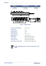
Mounting kit for SG-DM with SE-S column and floor stands

Figure 66 - Mounting kit

Mounting kit SG-DM on SG-PSB (ST-PS-DM)

Figure 67 - Mounting kit

MODEL

DESCRIPTION

CODE

ST-DM

SG-DM mounting kit (2 pcs kit)

95ASE1940

NOTE: For each SG-DM mirror order 1 mounting kit ST-DM.

MODEL

DESCRIPTION

CODE

ST-PS-DM

Deviating mirror SG-DM mounting kit (2 T-units)

95ASE1770

NOTE: For each SG-DM mirror order 1 mounting kit ST-PS-DM.

Summary of Contents for SH4 STANDARD MUTING

Page 1: ...SH4 STANDARD MUTING PRODUCT REFERENCE GUIDE Safety Light Curtains ...

Page 2: ...ned in this documentation and shall ensure that all notices appear on any reproductions of the documentation Electronic versions of this document may be downloaded from the Datasensing website www datasensing com Disclaimer Datasensing has taken reasonable measures to provide information in this manual that is complete and accurate however Datasensing shall not be liable for technical or editorial...

Page 3: ...tion distance 10 Practical examples 11 Typical applications 12 Example 1 Operating point protection on drilling machines 12 Example 2 Bending presses 12 Example 3 Paper cutting machines 13 Example 4 Milling machines 13 Safety information 14 General information on device positioning 15 Minimum distance from reflecting surface DSR 16 Distance between homologous devices 17 Emitter and receiver orient...

Page 4: ...ing 44 Configuration RX 44 Configuration TX 44 Test 45 Emission Range Selection SH4 x xxxx X models only 46 Muting 47 Configuration of Muting 48 Typical Muting application and safety light curtain connection 48 Muting mode selection 48 L muting 2 signals 2 sensors 49 T muting 2 signals 4 sensors 50 Partial Muting SH4 X XXXX SM 8 models only 51 Configuration 51 Muting signaling devices SH4 X XXXX S...

Page 5: ...racket 88 Protective tubes and stands 89 Protective Stands 89 Mounting kit 89 Plate Kit for Protective Stands 90 Mounting with SG P SB 90 Columns and floor stands 91 Mirrors 92 Deviating mirrors 92 Mounting kit for SG DM with SE S column and floor stands 93 Mounting kit SG DM on SG PSB ST PS DM 93 Connection cables 94 8 pole M12 cables Receiver main connector 94 5 pole M12 cables Transmitter main ...

Page 6: ...S vi SH4 STANDARD MUTING Protected Area 106 Operation 106 User Interface Dialogue 107 LED meanings 107 RX Side dialogue 108 TX Side dialogue 109 Response Time 110 Recovery Time 110 111 APPENDIX G GLOSSARY 112 ...

Page 7: ... observed when using the laser marker TECHNICAL SUPPORT Support Through the Website Datasensing provides several services as well as technical support through its website Log on to www datasensing com For quick access from the home page click on the search icon and type in the name of the product you re looking for This allows you access to download Data Sheets Manu als Software Utilities and Draw...

Page 8: ... whole unit consumable items 7 use of counterfeit or replacement parts that are neither manufactured nor approved by Datasensing for use in Datasensing manufactured Products 8 any damage or malfunctioning caused by non restoring action as for example firmware or software upgrades software or hardware reconfigurations etc 9 loss of data 10 any consumable or equivalent e g cables power supply batter...

Page 9: ...icular requirements for equipment using active optoelectronic pro tective devices EN ISO 13849 1 2015 Safety of machinery Safety related parts of control systems Part 1 General principles for design EN 61508 1 2010 Functional safety of electrical electronic programmable electronic safety related systems Part 1 General requirements EN 61508 2 2010 Functional safety of electrical electronic programm...

Page 10: ...e if correctly connected to the OSSD The SH4 safety light curtains are used in all automation fields where it is necessary to control and protect the access to dangerous zones In particular they are used in Manu facturing industry especially the three main vertical markets Automotive Electronics Food Beverage Most common vertical applications Robotics Metalworking Intra logistic and Material Handl...

Page 11: ...mm with 150 mm modularity BASE STANDARD STANDARD MUTING ADVANCED FUNCTION Automatic Restart Manual Automatic Restart Reset External Device Monitoring EDM Alignment Function 2 signals T Muting L Muting Single Override 2 signals muting dependent Override Partial muting half protection height Muting input filtering and timeout setting Anti interference coding 4 signals Muting Dynamic partial muting P...

Page 12: ...pean Declaration of Con formity is available at www datasensing com Select the link from the downloads sec tion of the product page UKCA Declaration of Conformity Hereby Datasensing S r l declares that the full text of the UKCA Declaration of Confor mity is available at www datasensing com Select the link from the downloads section of the product page ...

Page 13: ...COMPLIANCE PRODUCT REFERENCE GUIDE 5 ...

Page 14: ...ontains the following objects Receiver RX Emitter TX Quick Guide of safety light curtain Periodical checklist and maintenance schedule 4 angled fixing brackets and specific fasteners 2 additional angled fixing brackets for models with heights equal or greater than 1200 mm ...

Page 15: ...he ESPE must not be installed close to strong and or flashing light sources in par ticular close to the front window of receiving unit The presence of intense electromagnetic disturbances could affect device s cor rect operation This condition shall be carefully assessed with the advice of Datasensing Technical Service The operating distance of the device can be reduced in presence of smog fog or ...

Page 16: ...itute the detection zone and to actuate the sensing device The resolution is related to the part of the body to be protected As shown in the following figure the resolution only depends on the geometrical charac teristics of the lenses diameter and distance between centers and is independent of any environmental and operating conditions of the safety light curtain Figure 1 Detection capability The...

Page 17: ...the figure above the protected height is reported in the table here below MODEL PROTECTED HEIGHT mm SH4 14 30 0300 X X 300 SH4 14 30 0450 X X 450 SH4 14 30 0600 X X 600 SH4 14 30 0750 X X 750 SH4 14 30 0900 X X 900 SH4 14 30 1050 X X 1050 SH4 14 30 1200 X X 1200 SH4 14 30 1350 X X 1350 SH4 14 30 1500 X X 1500 SH4 14 30 1650 X X 1650 SH4 14 30 1800 X X 1800 SH4 14 30 1950 X X 1950 SH4 14 30 2100 X ...

Page 18: ...ositioning The following formula is used for the calculation of the safety distance S K t1 t2 C where S Minimum safety distance in mm K Speed of the object limb or body approaching the dangerous area in mm s t1 Response time of the ESPE in seconds see appendix Technical Data t2 Machine stopping time in seconds including the Safety Control System C Additional distance based on the possibility to in...

Page 19: ...cal examples Let s suppose to have a light curtain with height 600 mm To calculate the distance of the device from the ESPE in a vertical position the follow ing formula is used S K T C where S Minimum safety distance in mm t1 ESPE response time t2 Machine stopping time including the Safety Control System T t1 t2 Overall system stopping performance C 8 R 14 for devices with resolution 40 mm R Reso...

Page 20: ...rantees installation flexibility for machine dimensions Example 2 Bending presses The safety device must protect the operator from being squashed between the top and bottom tool or the machined part during the fast approach phase Solution If only one beam of the safety light curtain is darkened while the press is mov ing down the mobile tool bar will stop Advantages The safety light curtain can be...

Page 21: ... reduced profile and the two side slots ensure installation flexibility for machine dimensions Example 4 Milling machines A milling machine is a machine tool used for the shaping of metals and other solid mate rials Operator hands and body must be protected from being dragged entangled or cut by the tool spindle Solution SH4 30mm safety light curtain is the best solution considering the required s...

Page 22: ...safety light curtain must be securely placed in a particular position so that access to the dangerous zone is not possible without the interruption of the beams refer to Installation on page 6 The personnel operating in the dangerous area must be well trained and must have adequate knowledge of all the operating procedures of the safety light cur tain The TEST button must be located outside the da...

Page 23: ...le to install safety light curtain very near to the dangerous zone a second light curtain must be mounted in a horizontal position in order to prevent any lateral access as shown in the following figures CAUTION The figure below shows some examples of possible access to the machine from the top and the bottom sides These situations may be very dangerous and so the installation of the safety curtai...

Page 24: ...rtant to position the safety light curtain according to the minimum distance from reflecting surfaces The minimum distance depends on operating distance between emitter TX and receiver RX real aperture angle of ESPE EAA especially for ESPE Type 4 EAA 2 5 In the diagrams shows the minimum distance from the reflecting surface DSR based on the operating distance Figure 10 Minimum distance from reflec...

Page 25: ...minimum Ddo distance depends on the operating distance between emitter TXA and receiver RXA the effective aperture angle of the ESPE EAA Figure 12 ESPE Type 4 The formula to get Ddo is the following Ddo mm 263 for operating distance 3 m Ddo m operating distance m x tg 5 for operating distance 3 m CAUTION The interfering device TBX must be positioned at the same Ddo distance calculated as shown abo...

Page 26: ... figure provides two examples Figure 13 Recommended positioning for homologous devices CAUTION If two light curtains have to be mounted near each other as reported in the first example of the figure above TX TX TX TX TX TX RX RX RX RX RX RX ...

Page 27: ...pect to the beams Figure 15 Use of deviating mirrors The operator must respect the following precautions when using the deviating mirrors The alignment of the emitter and the receiver can be a very critical operation when deviating mirrors are used Even very small displacements of the mirror is enough to lose alignment The use of Datasensing laser pointer accessory is recommended under these con d...

Page 28: ...ed LED OSSD on RX side ON and controlled machine stop The response time at machine STOP including the ESPE and machine response times must be included in the limits defined in the calculation of the safety dis tance refer to Minimum installation distance starting on page 10 The safety distance between the dangerous parts and ESPE must comply with the requirements indicated in Minimum installation ...

Page 29: ...GENERAL INFORMATION ON DEVICE POSITIONING PRODUCT REFERENCE GUIDE 21 ...

Page 30: ...uded within the operating range of the model used see appendix Technical Data The two units must be positioned the most aligned and parallel possible The next step is the fine alignment as shown in the chapter Alignment Procedure Outfit angled fixing brackets kit for units mounting must be used as described below see Figure 17 Adjustable supports for adjusting unit inclinations around the axes are...

Page 31: ...x the bracket against the profile by tightening the M5 hexagonal nuts 3 4 It s possi ble to slide the bracket group along their dedicated rail and fix it once again just working on the above mentioned nuts Figure 17 Fixed brackets mounting procedure In case of applications with particularly strong vibrations vibration dampers together with mounting brackets are recommended to reduce the impact of ...

Page 32: ... 14 0900 x x SH4 30 0900 x x 909 509 200 SH4 14 1050 x x SH4 30 1050 x x 1059 609 225 SH4 14 1200 x x SH4 30 1200 x x 1209 909 150 454 5 SH4 14 1350 x x SH4 30 1350 x x 1359 1009 175 504 5 SH4 14 1500 x x SH4 30 1500 x x 1509 1109 200 554 5 SH4 14 1650 x x SH4 30 1650 x x 1659 1209 225 604 5 SH4 14 1800 x x SH4 30 1800 x x 1809 1309 250 654 5 SH4 14 1950 x x SH4 30 1950 x x 1959 1409 275 704 5 SH4...

Page 33: ...PRODUCT REFERENCE GUIDE 25 ...

Page 34: ...ARD MUTING CHAPTER 4 CONNECTIONS ELECTRICAL CONNECTION Pin out and configuration pin connection All electrical connections to the emitting and receiving units are made through M12 connector s Figure 20 Connections ...

Page 35: ...4 X XXXX SM 8 RECEIVER EMITTER RX M12 MALE 8 PIN TX M12 MALE 5 PIN 1 RESET RESTART EDM OVERRIDE white 1 24V brown 2 24V brown 2 TEST white 3 MUTING1 green 3 0V blue 4 MUTING2 yellow 4 CODE black 5 OSSD1 grey 5 COM grey 6 OSSD2 pink 7 0V blue 8 LAMP red ...

Page 36: ...ort circuited thus should be connected one side only 3 OVR1 green 3 0V blue 4 EDM yellow 4 CODE black 2 2 Pin 4 4 of male female connector are internally short circuited thus should be connected one side only 5 OSSD1 grey 5 COM grey 6 OSSD2 pink 7 0V blue 8 OVR2 red RX M12 FEMALE 5 PIN TX M12 FEMALE 5 PIN 1 24V OUT brown 1 24V OUT brown 2 MUT2 white 2 TEST white 3 0V OUT blue 3 0V OUT blue 4 MUT1 ...

Page 37: ...Automatic Restart mode left side and Manual Restart with monitoring right side Do not use varistors RC circuits or LEDs in parallel at relay inputs or in series at OSSD outputs The OSSD1 and OSSD2 safety contacts cannot be connected in series or in parallel but can be used separately conforming to the plant s safety requirements If one of these configurations is erroneously used the device enters ...

Page 38: ...ain has to control Figure 22 OSSDs connection Figure 23 Behavior of OSSDs OSSD1 OSSD2 OSSD1 OSSD2 OSSD1 OSSD2 OSSD2 OSSD1 24Vdc 24Vdc control by µpA control by µpB control by µpA control by µpB control by µpA control by µpB control by µpA control by µpB 24Vdc 24Vdc 24Vdc 24Vdc 24Vdc 24Vdc OSSD1 OSSD2 24Vdc 0Vdc 24Vdc 0Vdc 500 ms 1000ms 115 µs ...

Page 39: ...versa due to dust or vibration The alignment is perfect if the optic axes of the first and the last emitting unit s beams coincide with the optic axes of the corresponding elements of the receiving unit The figure shows that the first beam is located at the bottom edge of the light curtain near to connections The last beam is at the opposite side These two beams are the synchronization beams too F...

Page 40: ...beam received level gets some more weight SH4 X XXXX SM 8 5 models The ALIGNMENT function can be activated at power up keeping the RESET RESTART sig nal pin 1 HIGH for at least 0 5 seconds as shown in the following timing diagram When a good state of alignment is reached a power OFF and a power ON operation carry back the ESPE in normal operation In Alignment Mode ESPE is always in Safe State and ...

Page 41: ...evel is visualized on LED user interface LED meanings Table 1 User interface display in alignment mode INDICATION LED CONFIGURATION Not aligned Not aligned Only first sync aligned Not aligned Only last sync aligned Aligned Minimum Signal Level Aligned Medium Signal Level Maximum Signal Level F L 1 2 3 OFF ON BLINK INDIFFERENT ...

Page 42: ...d module OFF Minimum Signal Level weaker beam analog level 2 5V ON Medium Signal Level weaker beam analog level 3V ON Maximum Signal Level weaker beam analog level 3V ON NOTE On SH4 light curtains each optical module but the first 15 cm seg ment for 14 30 mm resolution will signal the status of its optics both in normal operation and alignment mode through a RGB module status LED Modules with inte...

Page 43: ... interface LED meanings Table 4 User interface display in alignment mode body INDICATION LED CONFIGURATION Not aligned Not aligned Only first sync aligned Not aligned Only last sync aligned LED user interface 1st module last module Nth module OFF ON BLINK INDIFFERENT First module Last module ...

Page 44: ...reon referred as SmartPlug Dip switches are present on RX unit only S 8 Models have a single 8 poles M12 connector with 2 muting signals inputs and over ride on a single wire S 8 5 Models have 2 connectors with 2 override signals inputs on main connector 2 muting signals inputs and power supply output for muting sensors on secondary con nector Can be also used as master in cascade configurations D...

Page 45: ...ction 6 OFF T ON L Muting Timeout 7 OFF 10 min ON infinite Muting Filter 8 OFF 100ms muting filter ON no muting filter FUNCTION DIP SETTINGS DEFAULT IN BOLD Override Trigger1 1 When Restart Mode is Manual a RESTART signal is requested at the end of Override sequence 1 OFF Level ON Edge Code 2 3 OFF OFF no code OFF ON code 1 ON OFF code 2 ON ON not used Configuration Failure if set EDM 4 OFF Disabl...

Page 46: ...ght Curtain 2 Set dip switch bank A all OFF 3 Set dip switch bank B all ON 4 Power ON the Safety Light Curtain 5 The Factory Reset signal is shown See User Interface Dialogue on page 61 6 Power OFF the Safety Light Curtain 7 Setting the Dip switches bank A and bank B according to the desired configura tion see Dip Switches on page 36 8 Power ON the Safety Light Curtain When reset is performed rela...

Page 47: ...rt When an opaque object is detected the ESPE enters in OFF state Then after the object has been removed from the controlled area the ESPE returns in ON state The response time is the time between the object introduction in the protected area and the OSSDs achieving the OFF state The recovery time is the time within OSSDs go in the ON state after the object is removed NOTE These times are function...

Page 48: ...e outputs go high after a time that is the maximum value between the recovery time and the time of restart low more or equal to 100 ms so this time can be any between 0 1 s and 5 s SH4 X XXXX SM 8 5 models Figure 26 OSSDs behavior in Manual Restart Mode and Restart Pattern SM 8 5 The outputs go high after a time that is the maximum value between the recovery time and the time of restart high more ...

Page 49: ...s and reset modes In applications protect ing access to dangerous areas the automatic reset mode is potentially unsafe if it allows the operator to pass completely beyond the sensitive area In this case the manual reset or for example the manual reset of the SE SR2 relay see Safety Units on page 96 is necessary Restart Mode 5 OFF Automatic ON Manual ...

Page 50: ... timing SM 8 If the error is not removed the light curtain goes in failure lockout again For a RESET to be performed two signal edge must be detected A timeout of 10s on the low RESET will cycle back the ESPE in lockout SH4 X XXXX SM 8 5 models Figure 28 Reset function timing SM 8 5 If the error is not removed the light curtain goes in failure lockout again For a RESET to be performed two signal e...

Page 51: ...below explains the relationship between the cause OSSDs and the effect EDM with the maximum permissible delay Figure 30 EDM function timing Tc 350 ms time between OSSD OFF ON transition and EDM test T0 100 ms time between OSSD ON OFF transition and EDM test two different times for the mechanical contact driven by a spring Configuration Set the Dip switch according to the chosen configuration 24Vdc...

Page 52: ...On RX unit set the Dip switch according to the chosen configuration Configuration TX TX unit will select emission code based on CODE input connection pin 4 M12 5 TX con nector at light curtain startup NOTE For correct light curtain operation both emitter and receiver unit must be configured with the same Coding setting Code 2 3 OFF OFF no code OFF ON code 1 ON OFF code 2 ON ON not used1 1 Configur...

Page 53: ... 0 5s plus a cycle time and after the response time of the light curtain Figure 31 OSSDs timing for test on TX NOTE On Body models only TEST input may be used to set Emission Range Refer to the next paragraph for more information CAUTION At runtime keep TEST input connected to 24Vdc for more than 2s and less than 5s to change range setting from Long to Short or vice versa Emission Range setting is...

Page 54: ...Emission Range Change Request timings 0 5s after rising edge on TEST input emission is disabled 2s after rising edge on TEST input Range Change Request is activated and both S and L led are lit on user interface If a falling edge is detected within 5s from rising edge emitter unit reboots with the new range If a falling edge is not detected within 5s from rising edge emitter unit locks into Range ...

Page 55: ...are activated by two Muting sensors or actuators these should be correctly connected and positioned in order to avoid undesired Muting or potentially dangerous conditions for the operator MUTING1 and MUTING2 can t be activated simultaneously State of Muting is signaled by an optional external Muting Lamp and by modules status LEDs on the user interface When the Muting function is ON the LAMP and t...

Page 56: ... bidirectional T type two sensors and monodirectional L type two sensors Muting Bidirectional Muting can be used in those applications in which the packs can move in both directions and mono directional Muting can be used only on those applications in which the packs moves out from the dangerous area Muting Direction 6 OFF T ON L Muting Timeout 7 OFF 10 min ON infinity Muting Filter 100ms 8 OFF 10...

Page 57: ...sed when 2xT12 timer expires starting from falling edge on MUTING1 input If MUTING2 input goes low before MUTING1 muting is ceased immediately Muting is optionally ceased also when light curtain is free before the timer expires Muting stop condition parameter Figure 37 L muting timings Figure 38 Connection of sensors on MUTING1 and MUTING2 inputs in case of monodirectional L two sensors muting NOT...

Page 58: ... than response time and less than 4s Figure 39 T muting timings Figure 40 Connection of sensors on MUTING1 and MUTING2 inputs in case of bidirectional T four sensors muting NOTE See Response Times on page 78 NOTE Muting operations is ceased as soon as the signal on MUTING1 or MUTING2 goes low MUTING1 24Vdc MUTING2 MUTING STATE 0Vdc 24Vdc 0Vdc ON OFF T12min T12 4 s T12min T12 4 s t muting timeout t...

Page 59: ...d beam zones Partial Muting can be useful in those applications in which the user wants to limit the Muting function effects to selected zones only Figure 41 Partial muting Configuration Set the Dip switch according to limit muting function effect to selected beam zones ZONE B ZONE A Partial Muting 1 OFF Total Muting ON Partial Muting ...

Page 60: ...utput pin 8 When a lamp is connected if a break is detected ESPE goes in Lamp Failure Lock Out state and shows the related message on the display refer to Technical Data on page 101 for information about the lamp output Electrical Connection Figure 42 Muting Signaling Device connection NOTE Both incandescent and LED lamps are allowed Proper polarity must be respected for the latter NOTE If an exte...

Page 61: ...ed because of ESPE detecting intercepted beams With Override activation nor mal operation is restored NOTE For the SH4 X XXXX SM 8 5 models two separate redundant inputs pin 3 OVR1 and pin 8 OVR2 have to be connected through one nor mally open contact to 24Vdc and one normally open contact to 0V thus to provide complementary inputs see SH4 X XXXX SM 8 5 models on page 54 NOTE For the SH4 X XXXX SM...

Page 62: ... be accepted is ESPE is in OFF state and at least one muting sensor is intercepted When such condition is verified user interface visualizes Override allowed with both red OSSD LEDs for the SH4 XX XXXX X models or with both red OSSD and blue 1C2 LEDs for the SH4 X XXXX X models Override allowed Override allowed OVERRIDE1 OVERRIDE2 24V dc NO NO ESPE ...

Page 63: ...il both contacts are closed AND at least one muting sensor is intercepted high input Figure 44 Level Triggered Override Timings Edge Trigger Edge Trigger override engaged on contacts closing until at least one muting sensor is intercepted Figure 45 Edge Triggered Override Timings 24Vdc Open Open 0Vdc TRUE FALSE ON OFF OVERRIDE STATE MUTING1 or MUTING2 OVERRIDE 2 OVERRIDE 1 t 400ms t 400ms t Tout 2...

Page 64: ... STANDARD MUTING Configuration Set the Dip switch according to the chosen configuration Override Trigger1 1 When Restart Mode is Manual a RESTART signal is requested at the end of Override sequence 1 OFF Level ON Edge ...

Page 65: ...ngle input provided that a specific signal pattern is respected The Override input pin 1 is shared with EDM feedback and Restart Two different way of starting OVERRIDE are provided Override at Startup on page 58 Override at Runtime on page 59 1 2 White Brown Test 24Vdc KM1 KM2 Restart Override ...

Page 66: ... any of the following conditions OR TEST button press release 2s after all beams are free After 10min timeout NOTE External lamp flashes when Override is active and user interface visualizes Override Active signals see Override Active on page 63 NOTE When Automatic Restart is selected OSSDs remains activated after Override ends NOTE When Manual Restart is selected restart contact must be open and ...

Page 67: ... the following conditions OR TEST button press release 2s after all beams are free After 10min timeout NOTE External lamp flashes when Override is active and user interface visualizes Override Active signals see Override Active on page 63 NOTE When Automatic Restart is selected OSSDs remains activated after Override ends NOTE When Manual Restart is selected restart contact must be open and closed ...

Page 68: ...FUNCTIONS 60 SH4 STANDARD MUTING ...

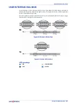
Page 69: ...state of the light curtain for alignment mode normal operation and for troubleshooting activity For each optical module on both RX and TX unit an RGB led will inform about single module status and light curtain operation Figure 49 Emitter LED interface LED meanings RX TX 1st module 2nd module Nth module Figure 48 Receiver LED interface 1st module 2nd module Nth module OFF ON BLINK INDIFFERENT ...

Page 70: ...ly last sync aligned Aligned Minimum Signal Level Aligned Medium Signal Level Aligned Maximum Signal Level Module signal status from 2nd module Good Signal on modules no optics intercepted Low Signal on modules no optics intercepted At least one optic intercepted on modules with blinking red light eg Modules with different signal levels Normal Operation Manual Restart Only Manual Restart configure...

Page 71: ...ride allowed Normal Operation OSSD ON Minimum Signal Level Good Signal Level Maximum Signal Level Muting Active Override Active Configuration Reset Default Performed Failure Lockout Power Supply Failure F11 OSSDs failure F22 Microprocessor Failure F33 Optics Failure EDM Failure Restart Failure F1122 Cascade Failure F2233 Configuration Failure F20 Lamp Failure F1133 Input Failure ...

Page 72: ...ide dialogue Failure NO Lockout F10 Override Failure ESPE WORKING MODE INDICATION LED CONFIGURATION Normal Operation Emission Active NO CODE CODE1 CODE2 Test Emission OFF Test Failure F1 Failure on microprocessor F2 Failure on optics FL Cascade Failure ...

Page 73: ... alignment mode normal operation and for troubleshooting activity For each optical module on both RX and TX unit an RGB led will inform about single module status and light curtain operation Figure 51 Emitter LED interface LED meanings RX TX Figure 50 Receiver LED interface LED user interface 1st module Nth module last module LED user interface OFF ON BLINK INDIFFERENT ...

Page 74: ...y last sync aligned Alignment Normal Operation Single Optic No Signal Level on Nth optic Low Signal Level on Nth optic Good Signal Level on Nth optic Normal Operation Manual Restart Only Manual Restart configured Interlock free beams restart required Normal Operation EDM Active CODE1 CODE2 NO CODE LED user interface Nth module First module Last module Nth module Nth module Nth module ...

Page 75: ...ation OSSD ON Muting Active Override Active Configuration Reset Default Performed Failure Lockout Power Supply Failure FER OSSDs failure F1 Microprocessor Failure F2 Optics Failure FE EDM Failure FR Reset Restart Failure F12 Configuration Failure Dip switch F12E Lamp Failure Not intercepted beams or intercepted beams in muting zone Intercepted beams outside the muting zone All beams All beams Firs...

Page 76: ...O Lockout ER Override Failure ESPE WORKING MODE INDICATION LED CONFIGURATION Normal Operation Emission Active NO CODE CODE1 CODE2 SHORT Range LONG Range Emission OFF Test Range Change Request Failure F1 Failure on microprocessor F2 Failure on optics FLS Range setting failure ...

Page 77: ...SH4 X XXXX 8 X MODELS PRODUCT REFERENCE GUIDE 69 ...

Page 78: ...side the OSSD outputs should open the red LED OSSD on RX side is ON and the controlled machine stops The response time upon machine STOP including response time of the ESPE and of the machine is within the limits defined for the calculation of the safety dis tance see Installation on page 6 The safety distance between the dangerous areas and the ESPE are in accordance with the instructions include...

Page 79: ...asensing is at your disposal to carry out the installation The device uses fuses that are not self resetting Consequently in presence of short cir cuits causing the cut off of these fuses both safety light curtains RX and TX shall be sent to Datasensing Repair Service Department A power failure caused by interferences may temporarily open the OSSD outputs or trig ger Safety State over connected sa...

Page 80: ... apply too much pressure on the surface in order to avoid making it opaque Please do not use on plastic surfaces or on light curtain painted surfaces alcohol or solvents wool or synthetic cloths paper or other abrasive materials PRODUCT DISPOSAL Under current Italian and European laws Datasensing is not obliged to take care of product disposal at the end of its life Datasensing recommends disposin...

Page 81: ...4 Vdc 20 a Emitter consumption TX 3 5 W max Receiver consumption RX 5 5 W max without load Outputs 2 OSSDs Outputs for all models 2 Auxiliary Outputs for SH4 XX XXXX A X X models only 1 Lamp Output for SH4 XX XXXX SM 8 models only Output current 250 mA max each output 500 mA total max current Output voltage ON min Power supply value less 1 V Output voltage OFF max 0 2 V Output capacitative load 1 ...

Page 82: ...m for 14 mm res 0 2 to 20 m for 30 mm res 0 5 to 15 m for body SHORT range 5 to 70 m for body LONG range EAA angle 2 5 at 3 meters Ambient light rejection EN 61496 2 2020 MECHANICAL AND ENVIRONMENTAL DATA Operating temperature 30 55 C Storage temperature 30 60 C Temperature class T6 Humidity 15 95 no condensation Mechanical protection IP67 IP65 EN 60529 Vibrations 10 mm 3g 5 to 150 Hz frequency EN...

Page 83: ...PRODUCT REFERENCE GUIDE 75 ...

Page 84: ...20575 1800 SH4 14 1950 SM 8 957920054 SH4 14 1950 SM 8 5 957920576 1950 SH4 14 2100 SM 8 957920055 SH4 14 2100 SM 8 5 957920577 2100 SH4 14 2250 SM 8 957920056 SH4 14 2250 SM 8 5 957920578 2250 SH4 30 0300 SM 8 957920099 SH4 30 0300 SM 8 5 957920085 30 mm HAND PROTECTION 300 SH4 30 0450 SM 8 957920100 SH4 30 0450 SM 8 5 957920086 450 SH4 30 0600 SM 8 957920101 SH4 30 0600 SM 8 5 957920087 600 SH4 ...

Page 85: ...0 MODEL SINGLE CONNECTOR ORDERING NUMBER MODEL DUAL CONNECTOR ORDERING NUMBER RESOLUTION PROTECTED HEIGHT mm PAIR MODEL RECEIVER MODEL EMITTER MODEL SH4 14 XXXX SM 8 SH4 14 XXXX SM R 8 SH4 14 XXXX T 5 SH4 14 XXXX SM 8 5 SH4 14 XXXX SM R 8 5 SH4 14 XXXX T 5 5 SH4 30 XXXX SM 8 SH4 30 XXXX SM R 8 SH4 30 XXXX T 5 SH4 30 XXXX SM 8 5 SH4 30 XXXX SM R 8 5 SH4 30 XXXX T 5 5 SH4 2 3 4 XXXX SM 8 SH4 2 3 4 X...

Page 86: ...x x 900 90 15 30 SH4 14 1050 x x 1050 105 16 33 SH4 14 1200 x x 1200 120 18 37 SH4 14 1350 x x 1350 135 20 41 SH4 14 1500 x x 1500 150 21 45 SH4 14 1650 x x 1650 165 23 49 SH4 14 1800 x x 1800 180 24 52 SH4 14 1950 x x 1950 195 26 56 SH4 14 2100 x x 2100 210 27 60 SH4 14 2250 x x 2250 225 29 64 MODEL CONTROLLED HEIGHT mm NO BEAMS RESPONSETIME ms AIC DISABLE RESPONSETIME ms AIC ENABLE SH4 30 0300 x...

Page 87: ...GUIDE 79 SH4 2 3 4 XXXX X X models MODEL CONTROLLED HEIGHT mm NO BEAMS RESPONSETIME ms AIC DISABLE RESPONSETIME ms AIC ENABLE SH4 2 0500 x x 500 2 12 23 SH4 3 0800 x x 800 3 15 27 SH4 4 0900 x x 900 4 15 29 SH4 4 1200 x x 1200 4 15 29 ...

Page 88: ...X 309 SH4 14 0450 X X 459 SH4 14 0600 X X 609 SH4 14 0750 X X 759 SH4 14 0900 X X 909 SH4 14 1050 X X 1059 SH4 14 1200 X X 1209 SH4 14 1350 X X 1359 SH4 14 1500 X X 1509 SH4 14 1650 X X 1659 SH4 14 1800 X X 1809 SH4 14 1950 X X 1959 SH4 14 2100 X X 2109 SH4 14 2250 X X 2259 dimensions are in mm ...

Page 89: ... SH4 30 0450 X X 459 SH4 30 0600 X X 609 SH4 30 0750 X X 759 SH4 30 0900 X X 909 SH4 30 1050 X X 1059 SH4 30 1200 X X 1209 SH4 30 1350 X X 1359 SH4 30 1500 X X 1509 SH4 30 1650 X X 1659 SH4 30 1800 X X 1809 SH4 30 1950 X X 1959 SH4 30 2100 X X 2109 SH4 30 2250 X X 2259 dimensions are in mm ...

Page 90: ...OVERALL DIMENSIONS 82 SH4 STANDARD MUTING SH4 2 3 4 XXXX X X dimensions are in mm MODEL L mm SH4 2 0500 X X 674 SH4 3 0800 X X 974 SH4 4 0900 X X 1074 SH4 4 1200 X X 1374 ...

Page 91: ...PRODUCT REFERENCE GUIDE 83 ...

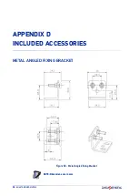
Page 92: ...84 SH4 STANDARD MUTING APPENDIX D INCLUDED ACCESSORIES METAL ANGLED FIXING BRACKET Figure 52 Metal Angled fixing Bracket NOTE Dimensions are in mm ...

Page 93: ...METAL ANGLED FIXING BRACKET PRODUCT REFERENCE GUIDE 85 ...

Page 94: ...86 SH4 STANDARD MUTING APPENDIX E ACCESSORIES BRACKETS Metal Angled Fixing Bracket Figure 53 ST KSTD MODEL DESCRIPTION CODE ST KSTD Angled fixing bracket 4 pcs kit 95ACC1670 NOTE Dimensions are in mm ...

Page 95: ... support Figure 56 Angled fixing bracket Anti vibration support Figure 57 Angled fixing bracket Orientable support Anti vibration support MODEL DESCRIPTION CODE ST K4OR Orientable supports 4 pcs kit 95ACC1680 ST K6OR Orientable supports 6 pcs kit 95ACC1690 ST K4AV Anti vibration supports 4 pcs kit 95ACC1700 ST K6AV Anti vibration supports 6 pcs kit 95ACC1710 NOTE Dimensions are in mm ...

Page 96: ...ACCESSORIES 88 SH4 STANDARD MUTING Rotating Bracket Figure 58 ST K4ROT SH MODEL DESCRIPTION CODE ST K4ROT SH Metal top bottom rotating fixing brackes kit 4 brackets for SH4 NOTE Dimensions are in mm ...

Page 97: ...ve stand H 600 mm 600 95ASE2240 SG PSB 1000 Protective stand H 1000 mm 1000 95ASE2250 SG PSB 1200 Protective stand H 1200 mm 1200 95ASE2260 SG PSB 1650 Protective stand H 1650 mm 1650 95ASE2270 SG PSB 1900 Protective stand H 1900 mm 1900 95ASE2280 NOTE Dimensions are in mm MODEL DESCRIPTION CODE ST PS4 SG SE Mounting kit 4 pcs kit 95ASE1750 ST PS6 SG SE Mounting kit 6 pcs kit 95ASE1760 NOTE Dimens...

Page 98: ...D MUTING Plate Kit for Protective Stands Figure 61 Plate kit Mounting with SG P SB Figure 62 Mounting with SG P SB MODEL DESCRIPTION CODE SG P Plate kit with springs 95ASE2290 NOTE Dimensions are in mm NOTE Dimensions are in mm ...

Page 99: ... X mm CODE SE S 800 Column and floor stand H 800 mm 800 30x30 95ACC1730 SE S 1000 Column and floor stand H 1000 mm 1000 30x30 95ACC1740 SE S 1200 Column and floor stand H 1200 mm 1200 30x30 95ACC1750 SE S 1500 Column and floor stand H 1500 mm 1500 45x45 95ACC1760 SE S 1800 Column and floor stand H 1800 mm 1800 45x45 95ACC1770 ...

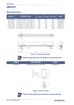
Page 100: ...version 900 mm 845 676 880 95ASE1690 SG DM 1200 Deviating mirror version 1200 mm 1145 976 1180 95ASE1700 SG DM 1650 Deviating mirror version 1650 mm 1595 1426 1630 95ASE1710 SG DM 1900 Deviating mirror version 1900 mm 1845 1676 1880 95ASE1720 NOTE The image includes the mirror SG DM and a mounting kit ST DM MODEL DESCRIPTION CODE SG DM 150 Deviating mirror version 150 mm 95ASE1670 NOTE The image i...

Page 101: ...ing kit SG DM on SG PSB ST PS DM Figure 67 Mounting kit MODEL DESCRIPTION CODE ST DM SG DM mounting kit 2 pcs kit 95ASE1940 NOTE For each SG DM mirror order 1 mounting kit ST DM MODEL DESCRIPTION CODE ST PS DM Deviating mirror SG DM mounting kit 2 T units 95ASE1770 NOTE For each SG DM mirror order 1 mounting kit ST PS DM ...

Page 102: ...4 95ASE1260 CS A1 06 U 50 8 pole M12 cable axial 50 m UL2464 95A252710 MODEL DESCRIPTION CODE CS A1 03 U 03 5 pole M12 cable axial 3 m UL2464 95ASE1170 CS A1 03 U 05 5 pole M12 cable axial 5 m UL2464 95ASE1180 CS A1 03 U 10 5 pole M12 cable axial 10 m UL2464 95ASE1190 CS A1 03 U 15 5 pole M12 cable axial 15 m UL2464 95ASE1200 CS A1 03 U 25 5 pole M12 cable axial 25 m UL2464 95ASE1210 CS A1 03 U 50...

Page 103: ... SH LP series represents a valid alignment and installation sup port for the safety light curtain series The pointer can be moved along the light curtain profile to verify the complete device alignment top and bottom Figure 68 Dimensions mm MODEL DESCRIPTION CODE SH LP Laser pointer 95ASE0030 ...

Page 104: ...n the safety light curtain and the Type 4 safety relay of the SE SR2 series operating in the automatic Restart mode Figure 69 Safety relay EDM relay box Figure 70 EMD relay MODEL DESCRIPTION CODE SE SR2 Type 4 safety relay 3 NQ 1 NC 95ACC6170 MODEL DESCRIPTION CODE CSME 03VU24 Y14 EDM relay 95ASE1270 ...

Page 105: ...Muting lamp 95ASE1830 LMS 1 Modular Muting lamp 95ACC1990 LMS 2 Muting lamp horizontal mounting 95ACC2000 LMS 3 Muting lamp vertical mounting 95ACC2010 SU LMS 1A Basic support for LMS 1 95ACC2020 SU LMS 1B Tower module for LMS 1 95ACC2030 Figure 71 Lamp LMS Figure 72 Lamp LMS 2 Figure 74 Module SU LMS 1A LMS 1 Figure 75 Module SU LMS 1B LMS 1 ...

Page 106: ...ssive arms with fixing bracket mounted of double active arms with fixing bracket mounted and of double passive arms with fixing bracket mounted SH T ARMS SH L ARMS MODEL DESCRIPTION CODE CV Y4 02 B 007 M12 4P T MUTING CABLE SH4 95ASE0037 CV L2 02 B 007 M12 4P L MUTING CABLE SH4 95ASE0038 MODEL DESCRIPTION CODE SH T ARMS T COUPLE ARMS 95ASE0035 SH L ARMS L COUPLE ARMS 95ASE0036 ...

Page 107: ...curtain dedicated muting connector via approx 0 5m long pigtail cable with M12 female connector Aside from the green LEDs1 to indicated sensors output status the SH M CB does not contain any electronic elements and is therefore not subject to any safety classification Features Supply and switching voltage 24Vdc M12 connection Simple connection to safety light curtains Figure 76 Connection box MODE...

Page 108: ...load max 1 A Insulating resistance 109 Ω Mechanical protection IP 67 Operating temperature 10 C 55 C Storage temperature 25 C 70 C Housing material PVC Black UL Recognized Housing cable C2 PVC Black UL Recognized Housing connector C1 Plug M12 5P A Coding Male Housing connectors A1 A2 B1 B2 Sockets M12 5P A Coding Female NOTE For each muting system kit the use of the same sensor type is recom mende...

Page 109: ...PRODUCT REFERENCE GUIDE 101 ...

Page 110: ...nctions as a single light curtains Advantages of cascading are better monitoring of dangerous areas with presence detec tion beyond the vertical detection zone and space and cost savings by using a single safety unit A cascade system will work as a single long unit where optic scan is synchronized between units in order to avoid mutual interferences A single couple of OSSDs outputs will reflect th...

Page 111: ...XXXX SM 8 5 or SH4 XX XXXX A 12 5 One LAST SLAVE unit can be chosen among SH4 XX XXXX B 5 or SH4 XX XXXX C 5 5 Optionally one MID SLAVE UNIT must be a SH4 XX XXXX C 5 5 unit Figure 79 Cascade system RX RX RX TX TX TX MASTER MID SLAVE LAST SLAVE SH4 XX XXXX SM 8 5 SH4 XX XXXX A 12 5 SH4 XX XXXX C 5 5 SH4 XX XXXX B 5 SH4 XX XXXX C 5 5 ...

Page 112: ...fer to Accessories appendix to see the available models NOTE When using a SH4 XX XXXX C 5 5 model as LAST SLAVE the M12 female connector will provide muting inputs with same pinout of MASTER unit depending on the configuration for advanced models For more details please refer to SH4 XX XXXX SM 8 5 or SH4 XX XXXX A 12 5 connections on the respective Product Reference Guide NOTE When using an SH4 XX...

Page 113: ...ions for consult the connector s pin out NOTE A safe auto recognition procedure at startup is implemented it automatically detects cascade topology and correctly address units M12 5 pin male M12 5 pin female M12 5 pin male M12 5 pin female M12 5 pin male M12 5 pin female or none ...

Page 114: ...h master and slaves unit stops into Communication Failure Lockout A maximum of one master and two slave units M S1 S2 can be connected in a cas cade 14mm and 30mm resolution can be mixed in a cascade system and as described in the previous chapter cascade system must have the following topology Cascade Topology units number length and resolution is auto detected at start up and stored in light cur...

Page 115: ...of the light curtain for alignment mode normal operation and for troubleshooting activity For each optical module on both RX and TX unit an RGB led will inform about single module status and light curtain operation Figure 81 Emitter LED interface LED meanings RX TX 1st module 2nd module Nth module Figure 80 Receiver LED interface 1st module 2nd module Nth module OFF ON BLINK INDIFFERENT ...

Page 116: ... light eg Modules with different signal levels Minimum Signal Level Maximum Signal Level Normal Operation OSSD OFF Invalid Blanking current unit or Muting Active or Override Active On models longer than 1200 only even modules blinking yellow Blanking on current unit Active Configuration GUI Configuration Pending Failure Lockout Slave units only show their error code F22 Microprocessor Failure F33 ...

Page 117: ...E PRODUCT REFERENCE GUIDE 109 TX Side dialogue ESPE WORKING MODE INDICATION LED CONFIGURATION Normal Operation Emission Active NO CODE CODE1 CODE2 Failure F1 Failure on microprocessor F2 Failure on optics FL Cascade Failure ...

Page 118: ...UNITS CASCADE Sum of units response times 1ms 3 UNITS CASCADE Sum of units response times 1ms RECOVERY TIME In cascade operation only receiver master unit synchronize with emitter master unit by means of two sync optics and respective unique patterns while TSCAN and TSELF TEST depend on all units operation see fig 47 For what said in 4 4 recovery time is equal to response time or 80ms whichever is...

Page 119: ...PRODUCT REFERENCE GUIDE 111 ...

Page 120: ...atter stops and keeps the machine stopped until the hazard is eliminated and then enters the dangerous area Now the safety device could not be able to prevent or avoid an unexpected restart of the machine with the operator still present inside the danger ous area Dangerous area Area representing an immediate or imminent physical hazard for the operator working inside it or who could get in contact...

Page 121: ...om the middle point of the detecting area to the nearest dangerous point Fac tors affecting min installation distance value are machine stop time total safety system response time and light curtain resolution MPCE Machine primary control element Electrically powered element having the direct control of machine regular operation so as to be the last element in order of time to operate when the mach...

Page 122: ... least one beam is intercepted OSSD LED lit RED in SLIM light curtain OSSD1 and OSSD2 are both switched OFF Safety light curtain It is an active optoelectronic protective device AOPD including an integrated system consisting of one or several emitting elements and one or several receiving elements forming a detection area with a detecting capacity specified by the supplier Start interlocking devic...

Page 123: ......

Page 124: ...it ing the rights under copyright no part of this documentation may be reproduced stored in or introduced into a retrieval system or transmitted in any form or by any means or for any purpose without the express written permission of Datasensing S r l Datasensing and the Datasensing logo are trademarks of Datasensing S r l www datasensing com 806000310 Rev A October 2022 ...

Reviews: