UM-0085-B09
DT80 Range User Manual
Page 279
RG
DT85/ DT85L/ DT85LM3
DT85G/ DT85GL/ DT85GLM3
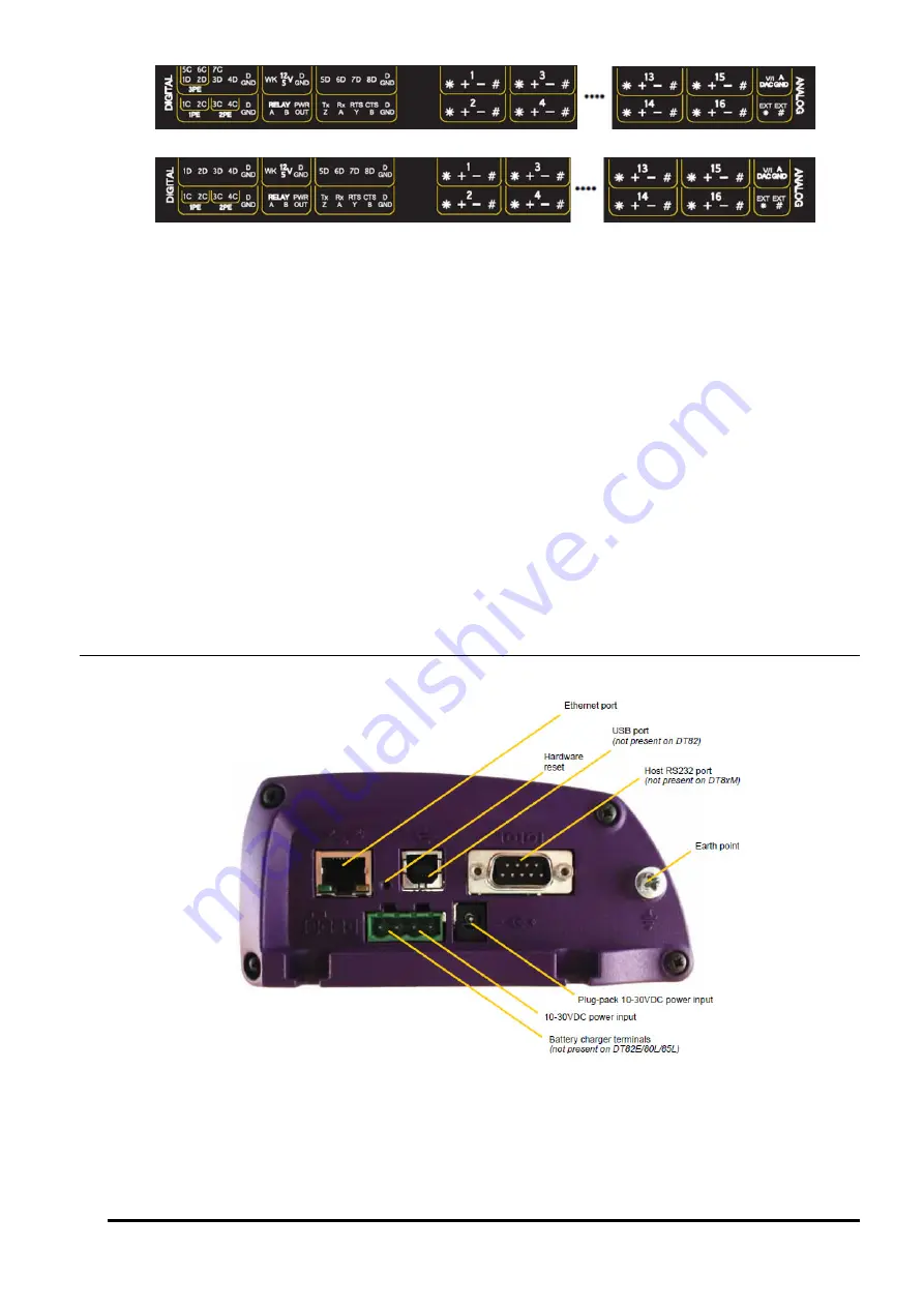
Figure 111: Standard terminal labels for DT80, DT82 and DT85 Series 4
The sensor interface comprises:
•
1D – 8D
: Digital Input/Output Channels
•
WK
:
Wake Terminal
•
12V
: 12V power output (not DT80/ 81 Series 1)
•
12V/ 5V:
12V or 5V controllable power output
(
Series 4 only
)
•
DGND
•
1C – 4C
: High Speed Counter Inputs
, shared with Phase Encoder Inputs (
1PE-2PE
)
•
5C – 7C
: High Speed Counter Inputs, shared with Phase Encoder Input (
3PE
) (DT85/ 85L Series 3 only)
•
RELAY
: Relay Output
•
PWR OUT
: Unswitched external power output (
DT85 only
)
•
Tx/Z Rx/A RTS/Y CTS/B
: Serial Sensor Port
•
1 – 16
(
* + – #
): Analog Input Channels
•
5V SW
: Isolated switched 5V output (
Series 3 only
)
•
V/I DAC:
Isolated 16bit voltage/current analog DAC output
(Series 4 only
)
•
AGND
: Analog Ground
•
EXT*
: External Excitation Input
•
EXT#
:
Switched Analog Ground
Left Side Panel
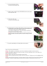
Figure 112: DT80 Left Side Panel
The
DT80
's side panel provides communications and power interfaces. Some models use cast endplates (as shown in
) while some use plain sheet metal endplates. However the layout of the ports is the same. Interfaces on the
side panel include:
•
Ethernet Port
•
USB Port
(not present on DT82E/ 82I/ 82EM)
•
RS232 Port
(not present on DT82EM/ 80LM/ 85LM/ 85GLM)


