UM-0085-B09
DT80 Range User Manual
Page 130
RG
Managing Schedules
To add a new schedule, select the
Add
menu, then
Schedule
. This will add a new entry to the tree view, and display it
with the name editable. Enter a name for the schedule then click the green tick.
To change the priority order of schedules, select a schedule on the tree and use the up/down arrow buttons at the bottom
of the tree view to move it up or down. Note that if the schedule order is changed then the schedule identifier (A, B etc.)
will change but the schedule name will remain the same. The topmost user schedule in the tree is always schedule A.
To delete a schedule and all of its constituent channels, select the schedule and click the Recycle Bin button.
Defining Channels
In the configuration builder, the
DT80
's channel types are categorised as follows:
•
Measurement
channels include all analog, digital and internal channel types
•
Control
channels are digital outputs
•
Serial
channels currently include the
SDI12
channel type only
•
Reference
,
Calculation
and
Delay
channels refer to the
&
chan
,
CALC
and
DELAY
channels
•
Action
channels allow certain commands to be inserted into a schedule. These will be placed inside a
DO{
...
}
block so that they will be executed when the schedule is triggered.
•
Manual
channels allow entry of a channel definition using the
DT80
command language. Use this for any
channel types not directly supported by the configuration builder.
To add a new channel:
1.
In the tree view, select the schedule to contain the new channel, or select any existing channel within that
schedule.
2.
Select the
Add
menu, then find the required channel type.
3.
An entry for the channel will be added to the tree. Enter a name for the channel, and click the green tick (or
press Enter).
4.
For most measurement channels, you now need to select a wiring diagram from the available choices on the
properties pane, and select the channel number.
5.
If required, the other channel options in the tabs in the lower part of the properties pane can now be set.
Note:
All channel names in a configuration must be unique.
Measurement and Serial Channels
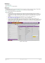
All measurement and serial channel types have a similar properties pane layout, as shown in
The control at the top of the screen specifies the specific channel type. In some cases this control is used to further refine
the channel type selected in the
Add
menu, in other cases it is a fixed value. In the example shown,
Thermocouple
was
selected in the
Add
menu, then
K-type thermocouple
was selected on this control.
Next comes the wiring configuration and channel number controls. These must both be set in order for the configuration
builder to generate a correct logger program.
The remainder of the options are presented in five tabs in the lower part of the properties pane. These all have default
settings; however you should check that these defaults match your requirements.
General Settings
The most important setting on this tab is the
Log and display this value
checkbox. For intermediate calculation
channels (working channels) this should normally be cleared to avoid cluttering the logged data with intermediate
channels.
Note that the configuration builder does not support individual control of channel value display, logging and return (
ND
,
NL
and
NR
channel options).
This tab also sets the units string that will be included in CSV data headings and shown on the display (assuming that
the "log and display" checkbox is ticked)
You can also assign the measured value to a channel variable. You may want to do this if the value is to be made
available to a Modbus client system, for example. If you want to use the value in a calculation, then it is easier to just use
a direct
reference
to the channel in the calculation; there is no need to assign it to a CV.
Some channel types may include other controls on this tab. For example, for an SDI-12 channel the device and register
addresses are specified here.


