UM-0085-B09
DT80 Range User Manual
Page 286
RG
Grounding
Note:
Protective earth must be installed for all of the installations where sensors and cabling is outdoors and is potentially subjected to
lighting strike.
Warning:
Correct grounding provides a safe discharge path for large electrical currents which may occur due to lightning or electrical
faults. When installing the
DT80
, consideration must be given to proper grounding, particularly where sensor or antenna cabling is
outdoors, and therefore potentially subject to lightning strike.
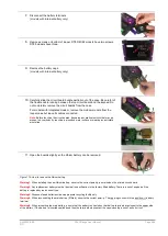
Figure 118: Protective earth connection
Some
DT80
models incorporate a
protective earth
connection. This is identified by the earth symbol enclosed in a
circle, as shown in Figure 107. Any ground point that is not marked with this symbol is a
functional earth
, and is not
suitable for a protective earth connection.
•
When installing a protective earth, note the following points:
•
The earth connection must be made by a qualified electrician.
•
The earth connector must be permanently connected to an earth ground as defined by the local wiring code.
•
The protective earth cable and connector are not supplied with the logger. Use connector and cable with a
minimum wire size of 14 AWG that are certified as appropriate for the country of installation.
•
Ensure the earth terminal screw is tightened properly to prevent accidental loosening.
Note:
All sensor cables that may be subject to lightning must have a maximum current rating of no more than 5A.
Powering the DT80
Power Subsystem
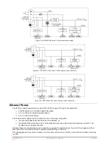
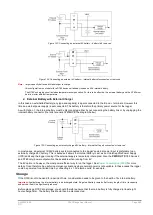
The following block diagrams give an overview of the
DT80's
internal
power subsystem.
Figure 119: DT80/ 82I/ 85 series 2 and 3 internal power subsystem


