UM-0085-B09
DT80 Range User Manual
Page 309
RG
Channel Options
The following channel options are commonly used when measuring resistances:
•
3W
(3 wire; default),
4W
(4 wire) or
2W
(2 wire; Series 3 only) specifies the type of resistance measurement
(number of wires)
•
I
(200μA excitation; default),
II
(2.5mA excitation) and
III
(2uA excitation) specifies the amount of current to
be passed through the resistance.
•
the
channel factor
specifies an offset adjustment (ohms) which is subtracted from the measured value. This
can be used to compensate for lead resistance in 2-wire configurations.
•
GL
x
,
ES
n
, as for voltage measurements
R1 – 4-Wire Resistance Inputs
Note:
In Series 4 loggers, this configuration is usable with excitation
III
for measuring up to 1MΩ
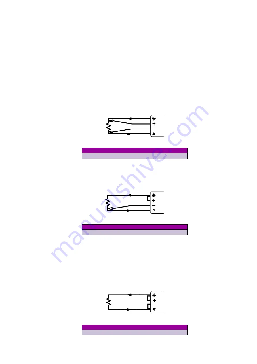
In this configuration the * and # terminals send an excitation current through the unknown resistance while the remaining
terminals sense the voltage across it.
4-wire resistance methods are the most accurate, especially for low resistances.
Figure 132: Wiring for 4-wire resistance input
To measure
Use the command
R
1R(4W)
R2 – 3-Wire Resistance Inputs
In this configuration the DT80 effectively measures the voltage drop in the return lead and uses it to compensate for the
voltage drop in both leads. This assumes the excitation and return lead resistances are equal.
See
for more details.
Figure 133: Wiring for 3-wire resistance input
To measure
Use the command
R
1R
R3 – 2-Wire Resistance Inputs
2-wire configurations are only recommended if the lead resistance is negligible compared to the resistance being
measured.
You can, however, compensate for the lead resistance by inserting a resistor equal to the total lead resistance (excite
lead resi return lead resistance) between the – and # terminals, in place of the link shown. This uses the DT80's
3-wire compensation circuit to effectively subtract the measured voltage drop across the resistor from the reading.
Alternatively, the total lead resistance could be specified as the channel factor, e.g. if the total lead resistance is known to
be 2.8
Ω
then you would specify the channel as
1R(2.8)
. (This assumes that the lead resistance remains fixed, which
may not be the case if the temperature varies).
Figure 134: Wiring for 2-wire resistance input
To measure
Use the command
R
1R


