The 8254-2 timer/counter is treated by system programs as an arran-
gement of four programmable external I/O ports. Three are treated as
counters; the fourth is a control register for mode programming.
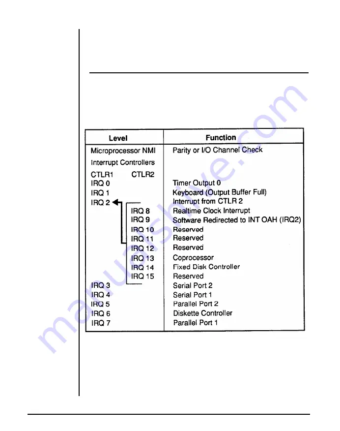
System interrupts
Si
an
interrupt-level assignments’ decreasing priority:
xteen levels of system interrupts are provided by the 80386SX NMI
d two
8259A
interrupt controller chips. The following shows the
T
able 6-4: Interrupt Level Assignment
Chapter 6: Appendix
19
Summary of Contents for Apex 386SX/20
Page 1: ...PEER 2030 2 O M H z 3 8 6 S X S Y S T E M U ser s Manual ...
Page 15: ...Chapter 1 System Overview ...
Page 38: ...Chapter 2 Setting Up Your System ...
Page 43: ...Figure 2 2 The Location of W9 80386SX and 80387SX Chapter 2 Setting Up Your System 5 ...
Page 48: ...Figure 2 6 512KB Total Onboard System Memory 10 Chapter 2 Setting Up Your System ...
Page 49: ...Figure 2 7 640 KB Total Onboard System Memory Chapter 2 Setting Up Your System 11 ...
Page 50: ...Figure 2 8 1 MB Total Onboard System Memory 12 Chapter 2 Setting Up Your System ...
Page 51: ...Figure 2 9 1 5 MB Total Onboard System Memory Chapter 2 Setting Up Your System 13 ...
Page 52: ...Figure 2 11 2MB Total Onboard System Memory B 14 Chapter 2 Setting Up Your System ...
Page 53: ...Figure 2 12 3MB Total Onboard System Memory Chapter 2 Setting Up Your System 15 ...
Page 54: ...Figure 2 13 4MB Total Onboard System Memory 16 Chapter 2 Setting Up Your System ...
Page 55: ...Figure 2 14 5MB Total Onboard System Memory Chapter 2 Setting Up Your System 17 ...
Page 61: ...Chapter 3 Operating Your System ...
Page 80: ...Chapter 4 Keyboard ...
Page 90: ...Chapter 5 Troubleshooting ...
Page 98: ...Appendix ...
Page 123: ...Chapter 7 Glossary ...


