HARDWARE INSTALLATION
61
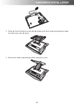
6. Align and install the cable compartment and the connectors covers.
Installing the VESA Mount (Optional)
NOTE:
• Use only wall mount kits approved by the manufacturer. Wall mount kits are sold
separately.
• The Touch Terminal device is compatible with a VESA mounting hole pattern of
75x75mm.
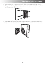
1. Place the Touch Terminal on a soft and flat surface, with the LCD panel facing down.
Remove the two screws (F
⊕
M4x10) on the hinge cover. Then remove the hinge cover.
Summary of Contents for G-615S
Page 1: ...Glamor Series G 615S G 715S G 715SR User s Manual V2 0 ...
Page 12: ...12 INTRODUCTION LCM VFD Customer Display 227 406 278 6 290 747 210 210 3 0 6 0 45 45 45 45 ...
Page 25: ...PREPARING FOR THE INSTALLATION 25 G 715S G 715SR Top View ...


