24
PREPARING FOR THE INSTALLATION
PREPARING FOR THE INSTALLATION
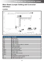
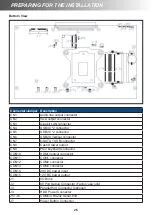
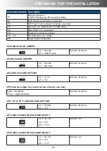
Connector/Jumper Description
J5
M/B Signal convergence connector
J6
System Function Connector
J7
SATA3.0 2.5” HDD/SSD 7+15PIN Dock
J8
DDR3L SO-DIMM (channel 1)
J9
DDR3L SO-DIMM (channel 2)
J10
Power Button Connector
J11
Mini PCIE V1.2 Connector
JP1
SPI Flash Tool Connector (Factory use only)
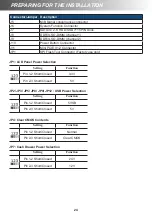
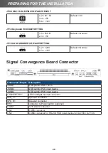
JP1: LCD Panel Power Selection
Setting
Function
Pin 1-2 Short/Closed
3.3V
Pin 2-3 Short/Closed
5V
JP2/ JP3/ JP5/ JP8/ JP9/ JP12 : USB Power Selection
Setting
Function
Pin 1-2 Short/Closed
5VSB
Pin 2-3 Short/Closed
5V
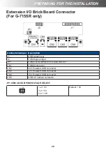
JP4: Clear CMOS Contents
Setting
Function
Pin 1-2 Short/Closed
Normal
Pin 2-3 Short/Closed
Clear CMOS
JP7: Cash Drawer Power Selection
Setting
Function
Pin 1-2 Short/Closed
24V
Pin 2-3 Short/Closed
12V


