19
The
Connection screen
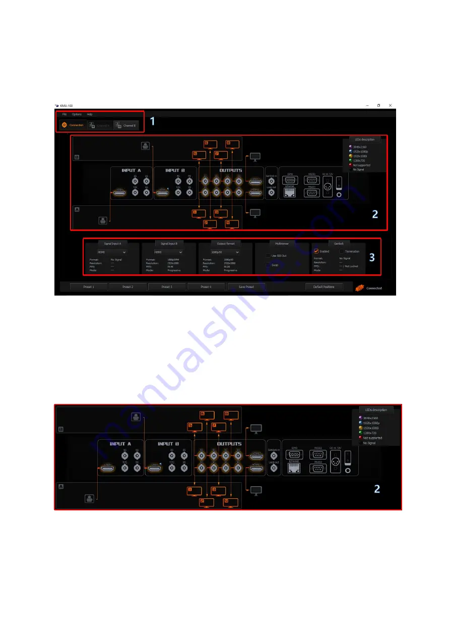
window can be divided into 3 areas as shown in the diagram below.
1.
Menu area
2.
Connection Graphics area
3.
Input/Output Signals area
1.
Menu area
– When the
Connection
tab turns orange, it indicates that you are working on
this particular screen. Pressing the
Channel A
or
Channel B
tabs will switch your display
from
Connection
mode to
Channel A
or
Channel B
setting (processing) mode. Detailed
explanations of the
Menu area
is in later parts of the manual.
2.
Connection
Graphics area
– The Connection Graphics Area is basically a graphical
visualization of the rear panel of the
KMU-100
device with all its available
inputs and
outputs
. The active status and the introduced changes to the inputs and outputs are
graphically shown on the screen in the form of arrows / orange icons.
In fact, the active
inputs / outputs
on the rear panel of the
KMU-100
device are indicated by
glowing
LEDs
at each
input / output port
. Color of the diode represents the signal resolution.
The LED lights up when a signal is detected at the input.
Summary of Contents for KMU-100
Page 1: ...PROCESSOR Instruction Manual ...
Page 54: ...54 11 System Diagram of the RMC 185 and KMU 100 Connection ...
Page 62: ...62 Power On Off Switch Switches the device ON OFF ...
Page 81: ...81 21 Dimensions KMU 100 KMU 100 ...
Page 82: ...82 RMC 185 RMC 185 Unit mm ...
Page 86: ...86 Note ...
Page 87: ...87 Note ...


