background image

11 


R                               B 


R              G              B 

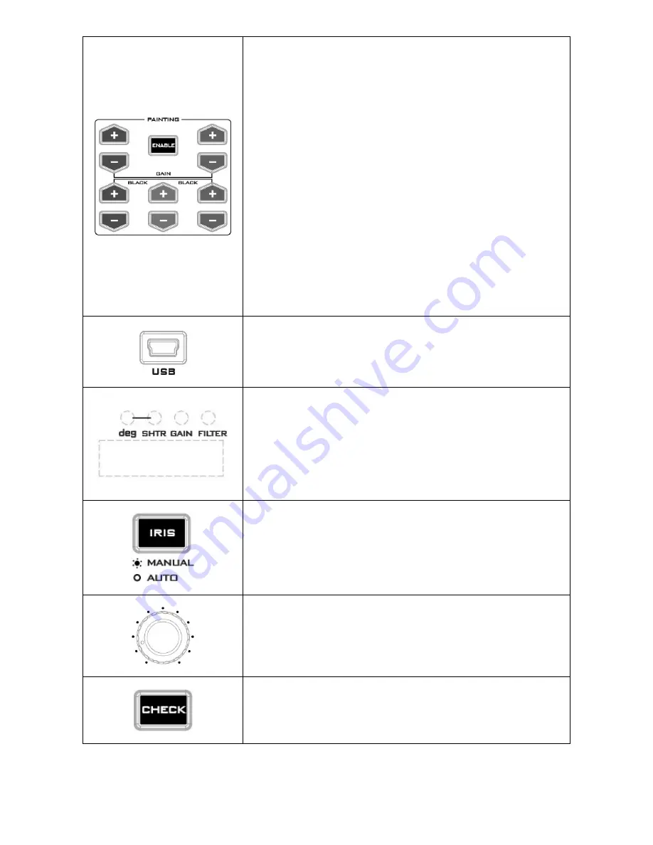
Enable & Painting Adjustment buttons 

-


Press the 

ENABLE

 button in the 

Painting area

 of the MCU-

100J  before choosing to adjust either the level of the Red 

and Blue Gain or the RGB Pedestal values.  

-


Once pressed, the 

ENABLE

  button  will turn red and all +/- 

buttons will turn white.  

-


Press again to turn off the 

ENABLE

  button (white), and all 

other +/-  button will be disabled with the button LEDs 

turned off.  


Fast zeroing of parameters 

1.


Press and hold the ENABLE button until the +/- button LEDs 

start flashing. 

2.


Press one of the corresp/- buttons to reset R Gain, B 

Gain, R Black, and B Black to default (128). 

3.


If nothing is pressed, the button LEDs will stop flashing and 

return to normal after 10 seconds. 


Mini USB 2.0 port 

This port is used for firmware updates or to save/transfer MCU-

100J  settings to computer. See 

page 14

  for firmware update 

details. 


LED display 

The IRIS Value, Shutter Degree, and Gain can be displayed here 

by pressing the IRIS button. 


Note

:  The IRIS value displayed on the camera’s LCD panel is 

usually more precise than the IRIS value displayed on the MCU-

100J LED display.  


IRIS button 

To enable or disable Auto Iris.  


The button is backlit red when MANUAL Iris is enabled.  


IRIS control 

Used to adjust the Iris value. See IRIS button also. 


Check button 

No function


Summary of Contents for MCU-100J

Page 1: ......

Page 2: ...COMPATIBLE CAMERA MODELS 5 SYSTEM DIAGRAM 6 CONNECTIONS AND CONTROLS 7 MCU 100J KEYBOARD 7 MCU 100J FRONT PANEL 7 MCU 100J KEYBOARD GUIDE 8 SEVEN SEGMENT DISPLAY AND LEDS 12 VERSION NUMBER DISPLAY AN...

Page 3: ...hat the total of the ampere ratings on the products plugged into the extension cord do not exceed the extension cord rating 10 Make sure that the total amperes of all the units that are plugged into a...

Page 4: ...lease visit www datavideo com or contact your local Datavideo office or authorized Distributors Certain parts with limited lifetime expectancy such as LCD Panels DVD Drives Hard Drives are only covere...

Page 5: ...o four JVC cameras RJ 45 cabling allows the unit to be placed up to 300m away from the camera s Support LANC multicore control interface Control of Record and Record review functions Control of Camera...

Page 6: ...6 System Diagram...

Page 7: ...J Front Panel Remote Control RJ 45 Interface 12V DC Input Cameral Select White Black Balance USB for F W Update IRIS Adjustment LED Display Gain IRIS Adjustment Power Master Pedestal Control Enable Pa...

Page 8: ...focus Note If camera focus is not triggered after this button is pressed push and hold the button till your camera s focus setting starts to change Focus Far x 1 Far field focus x 1 Note If camera fo...

Page 9: ...tions Pressing the same dial like a button confirms the current selection or value shown When the MENU button is NOT activated and back lit green The select dial is used to adjust the SHUTTER speed of...

Page 10: ...ignal BARS Camera generated colour bar output CAM AUTO KNEE OFF Output is the camera shot The AUTO KNEE circuit is disabled MANUAL KNEE is set as the camera recorder s initial setting CAM AUTO KNEE ON...

Page 11: ...ttons to reset R Gain B Gain R Black and B Black to default 128 3 If nothing is pressed the button LEDs will stop flashing and return to normal after 10 seconds Mini USB 2 0 port This port is used for...

Page 12: ...F1 1 Rotate SEL knob to cycle through F1 1 F1 2 and F1 3 on the seven segment display Press SEL knob to enter the individual F1 functions The table below contains descriptions of each individual F1 fu...

Page 13: ...AIN PUSH AF AUTO Master Pedestal FOCUS NEAR R B gain FOCUS NEAR x 1 speed FOCUS FAR FOCUS FAR x 1 speed IRIS IRIS DISP INFO REC REVIEW Assign NOTE For camera with the MCU 100J connected please set cam...

Page 14: ...irmware of the AD 1J unit s at the same time as the MCU 100J How to update the MCU 100J firmware 1 Turn off the MCU 100J device power 2 Connect the MCU 100J to PC via a USB cable 3 Set the five switch...

Page 15: ...15 Dimensions Specifications Power Consumption DC 12V 0 5A 6W Weight 350 g Dimension 95mm W x 208mm H x 65 5mm D Input Output Connection RJ45 x 4 Connection Distance Up to 300m CAT 5 5e or CAT6...

Page 16: ...16 Service Support...

Reviews: