background image

13 


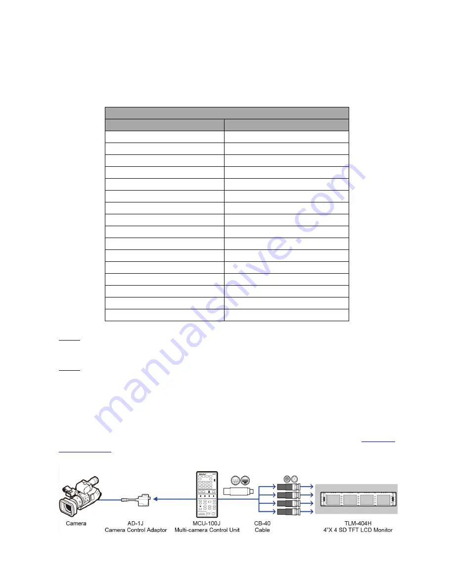
This unit allows you to operate the JVC camera with the MCU-100J unit at a distance of up to 300m 

away from the camera.  


The AD-1J  adaptor  connects  the MCU-100J  to the selected  JVC  camera  via  an  RJ-45 cable. This 

adaptor adapts the RJ-45 connection to a JVC LANC and PS/2 Control Interface.  


The table below lists all the functions that can be controlled via LANC and PS/2 Control Interfaces. 


MCU-100J Command 

LANC 

Multicore PS/2  

REC ON/OFF 

Shutter 

ZOOM WIDE 

AWB 

ZOOM TELE 

W.BAL 

ZOOM WIDE (2 speed) 

KNEE 

ZOOM TELE (2 speed) 

COLOR BAR 

CHANGE AF MANUAL/AUTO 

GAIN 

PUSH AF AUTO 

Master Pedestal  

FOCUS NEAR 

R & B gain 

FOCUS NEAR x 1 speed 


FOCUS FAR 


FOCUS FAR x 1 speed 


IRIS+ 


IRIS- 


DISP INFO 


REC REVIEW 


Assign 


NOTE:

 For camera with the MCU-100J connected, please set camera remote control function to 

ON and then connect the MCU-100J and AD-1J. 


NOTE:

  With the AD-1J  connected, the menu and other functions of the JVC  camera may be 

limited to remote control only. To regain manual control of the menu functions on the camera, 

the user should first disconnect the AD-1J. 


Each AD-1J  adaptor has a built in Velcro strap so that the unit can be quickly mounted in a 

convenient location on or near the camera. 


A micro USB 2.0 port is provided for transfer of firmware updates to the unit. See 

Firmware 

Update Section


for more details. 


Summary of Contents for MCU-100J

Page 1: ......

Page 2: ...COMPATIBLE CAMERA MODELS 5 SYSTEM DIAGRAM 6 CONNECTIONS AND CONTROLS 7 MCU 100J KEYBOARD 7 MCU 100J FRONT PANEL 7 MCU 100J KEYBOARD GUIDE 8 SEVEN SEGMENT DISPLAY AND LEDS 12 VERSION NUMBER DISPLAY AN...

Page 3: ...hat the total of the ampere ratings on the products plugged into the extension cord do not exceed the extension cord rating 10 Make sure that the total amperes of all the units that are plugged into a...

Page 4: ...lease visit www datavideo com or contact your local Datavideo office or authorized Distributors Certain parts with limited lifetime expectancy such as LCD Panels DVD Drives Hard Drives are only covere...

Page 5: ...o four JVC cameras RJ 45 cabling allows the unit to be placed up to 300m away from the camera s Support LANC multicore control interface Control of Record and Record review functions Control of Camera...

Page 6: ...6 System Diagram...

Page 7: ...J Front Panel Remote Control RJ 45 Interface 12V DC Input Cameral Select White Black Balance USB for F W Update IRIS Adjustment LED Display Gain IRIS Adjustment Power Master Pedestal Control Enable Pa...

Page 8: ...focus Note If camera focus is not triggered after this button is pressed push and hold the button till your camera s focus setting starts to change Focus Far x 1 Far field focus x 1 Note If camera fo...

Page 9: ...tions Pressing the same dial like a button confirms the current selection or value shown When the MENU button is NOT activated and back lit green The select dial is used to adjust the SHUTTER speed of...

Page 10: ...ignal BARS Camera generated colour bar output CAM AUTO KNEE OFF Output is the camera shot The AUTO KNEE circuit is disabled MANUAL KNEE is set as the camera recorder s initial setting CAM AUTO KNEE ON...

Page 11: ...ttons to reset R Gain B Gain R Black and B Black to default 128 3 If nothing is pressed the button LEDs will stop flashing and return to normal after 10 seconds Mini USB 2 0 port This port is used for...

Page 12: ...F1 1 Rotate SEL knob to cycle through F1 1 F1 2 and F1 3 on the seven segment display Press SEL knob to enter the individual F1 functions The table below contains descriptions of each individual F1 fu...

Page 13: ...AIN PUSH AF AUTO Master Pedestal FOCUS NEAR R B gain FOCUS NEAR x 1 speed FOCUS FAR FOCUS FAR x 1 speed IRIS IRIS DISP INFO REC REVIEW Assign NOTE For camera with the MCU 100J connected please set cam...

Page 14: ...irmware of the AD 1J unit s at the same time as the MCU 100J How to update the MCU 100J firmware 1 Turn off the MCU 100J device power 2 Connect the MCU 100J to PC via a USB cable 3 Set the five switch...

Page 15: ...15 Dimensions Specifications Power Consumption DC 12V 0 5A 6W Weight 350 g Dimension 95mm W x 208mm H x 65 5mm D Input Output Connection RJ45 x 4 Connection Distance Up to 300m CAT 5 5e or CAT6...

Page 16: ...16 Service Support...

Reviews: