background image

DT9100 B

7.3. Second clear

 (01. menu item)

Function

Set the seconds of time to zero, and round time.
If the moment of button pressing the second was between 
0 and 29, the hour and minute not changing. 
If the moment of button pressing the second was between 
30 and 59, the minute rounding up (if necessary the hour 
too). 

Sequence of operations

1. Enter the menu by the user or the supervisor code.
Chapter 7.1. Type in the code (password) describes how 
you can it. You will see on the display: 



.

2. Enter this menu item by the 

ENTER

 button.

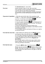
3. You will see the mnemonic 



on the display for 3 

seconds, the time appears in MM.SS format. The decimal 
point is blinking per second.
4. Press the ▲ button to set the seconds to zero. 
Seconds are rounded down between 0 and 29 and rounded
up between 30 and 59.
5. Press MENU button to set the time (if there is no need to
set seconds to zero).

Exit from the menu item

1. After finishing the settings, press the 

MENU

 button to 

exit the given menu item, and will you see: 



.

(2. If you want to change the settings you have just done, 
or if you just want to check what you have typed in, go on 
with the operation from point 2 of the 

Sequence of 

operations

.)

(3. If you don’t want to exit the menu (you want to make 
further settings), then you may select the desired menu 
items by pressing the ▲ button.)

Exit from the menu

1. Press the 

MENU

 button. First the mnemonic 




(

Save

), then the mnemonic 



 (

Exit

) are shown on the

display. With that, the storing of the settings is completed. 
The instrument has exited the menu and goes on with the 
measurement.

20180905-V1

31

Summary of Contents for DT9100 B

Page 1: ...DT9100 B Intrinsically Safe Digital Clock Operating Instructions...

Page 2: ...of operation 8 3 3 Adjustment 9 3 4 Storage and transport 9 4 Mounting 10 4 1 General instructions 10 4 2 Main dimensions of the instrument 11 4 3 Mounting as a wall instrument 12 4 4 Mounting as a pa...

Page 3: ...Digital output 2 08 menu item 39 7 11 Changing the supervisor code 09 menu item 40 7 12 Tests 10 menu item 42 8 Fault rectification 44 8 1 Fault finding 44 8 2 Repairing 44 9 Dismounting 44 9 1 Dismou...

Page 4: ...nnel and put into practice by them 1 3 Symbolism used Information tip note This symbol indicates helpful additional information Caution warning danger This symbol informs you of a dangerous situation...

Page 5: ...ut misuse Inappropriate or incorrect use of the instrument can give rise to application specific hazards or damage to system components through incorrect mounting or adjustment 2 4 General safety inst...

Page 6: ...fety instructions are part of the operating instructions and come with the Ex approved instruments 2 7 Environmental instructions Protection of the environment is one of our most important duties Plea...

Page 7: ...ply 1 pc M16x1 5 cable entry accessory 2 pcs of screw clamps only for the panel mounted version instrument sealing only for the panel mounted version documentation this operating instructions certific...

Page 8: ...stallation in the field or on a control panel Operating principle The clock incorporates a high accuracy temperature compensated time base which is processed by a microcontroller The microcontroller p...

Page 9: ...nstrument should be stored and transported in places whose climatic conditions are in accordance with the conditions described under the title Environmental conditions in Chapter 10 1 Technical specif...

Page 10: ...sition where you can easily read the display which is accessible for mounting and connecting the instrument and which minimises the hazard of water dust or dump getting into the instrument The recomme...

Page 11: ...DT9100 B 4 2 Main dimensions of the instrument Wall mounted instrument Panel mounted instrument 20180905 V1 11...

Page 12: ...may cause damage to the screws heads or to the instrument front panel Remove the screws by turning them in an anticlockwise direction as shown in the drawing Step 1 The screws are secured against fal...

Page 13: ...stening of the housing The diameters of the holes are made for M3 screws Holes for mounting 1 Mark the places of the holes in accordance with the drawing 2 Make the holes ready for mounting 3 Remove a...

Page 14: ...rial of the wall and in order to ensure the most practicable mounting method it is not mandatory of course to use the above described threaded joints Depending on the situation special screw types for...

Page 15: ...panel instrument Preparatory steps 1 Cut a piece out of the panel according to the figure shown below The cutting requires special tools it must be carried out by trained specialist personnel Cut out...

Page 16: ...ument into the prepared cut out as much as possible and check the fitting of the seal between case and mounting surface 4 Put on the enclosed screw clamps onto the sides of the instrument case Figure...

Page 17: ...Use two wire twisted pair screened cable The wire cross section should be 0 25 1 5 mm2 You may use either solid conductor or flexible conductor In the case of using flexible conductor use crimped wire...

Page 18: ...s and to form the shields as shown in the diagram A common cable can only be used if the insulation strength between the wires is 500 V or higher Cables entries 1 Check the conformity of the cables as...

Page 19: ...lexible cable ends you can facilitate opening the connection part by pushing down the white button 2 By pushing the wire in the self closing connection is being established Check it by pulling it outw...

Page 20: ...ity with the following input parameters Uo 30 V Io 200 mA Po 0 75 W The following figure shows the connection Wiring plan connecting the synchrinising input see also Application example Be careful wit...

Page 21: ...formity with the following output parameters Uo 10 V Io 200 mA Po 0 5 W The following figure shows the connection Wiring plan connecting the digital outputs see also Application example Be careful wit...

Page 22: ...pack Be careful with the polarity of the cables 1 Push the cable end into the terminal assembly as far as possible By pushing the wire in the self closing connection is being established 2 Check it b...

Page 23: ...eplaceable battery pack which will operate the clock for at least two years The battery connection or replacement can be accomplished even in hazardous areas Do not use other battery type The followin...

Page 24: ...o the right place are not the cable ends touching each other 8 Mount the instrument front cover as it is written in Chapter 4 3 Finishing steps 1 Check if the cables are connected properly have you co...

Page 25: ...power supply Initialization Factory default In the case of an error message If anything else appears on the display instead of the numbers showing the current value e g a message with blinking letter...

Page 26: ...Z All mnemonics code words presented on the display come from English expressions in abbreviated forms The following part gives a list of the possible mnemonics and their meanings The left side colum...

Page 27: ...k place Supervisor During setting up Bad input value Error Retype it please Retype Automatic escaping Time Out after 4 minute Exit from the setting Exit Enter menu of second clearing The requested ope...

Page 28: ...s been given it enters into the menu During this time the clock is running and the digital outputs don t change If no keys are pressed for a period of one minute the instrument restarts and the measur...

Page 29: ...to select the next digit 3 By pressing the and the buttons type in either the user code or the supervisor code 4 Press the MENU button If a correct code has been type in the login as a user or login a...

Page 30: ...e 04 Synchronisation mode 35 page 05 Synchronisation time 36 page 06 Sync gate time 37 page 07 Digital output 1 38 page 08 Digital output 2 39 page 09 Supervisor code 40 page 10 Tests 42 page Comment...

Page 31: ...to set the seconds to zero Seconds are rounded down between 0 and 29 and rounded up between 30 and 59 5 Press MENU button to set the time if there is no need to set seconds to zero Exit from the menu...

Page 32: ...xt digit so you can set all the four digits after the 4th digit the 1st digit will appear Exit from the menu item 1 After finishing the settings press the MENU button to exit the given menu item and t...

Page 33: ...blinking By pressing the button you can increase the value of the blinking digit etc By pressing the button you can select the next digit 3 By pressing the buttons and type in the new user code 4 Pre...

Page 34: ...u item Changing the user code you will see this 2 If you want to change the setting you have just performed or if you just want to check what you have typed in continue the operation from Point 3 of t...

Page 35: ...ation factory setting synchronisation of seconds synchronisation at the time given in menu item Exit from the menu item 1 After finishing the setting press the MENU button to exit the menu item and yo...

Page 36: ...tton you can select the next digit so you can set all the four digits after the 4th digit the 1st digit will appear Exit from the menu item 1 After finishing the setting press the MENU button to exit...

Page 37: ...e password You will see on the display 2 Keep stepping by pressing the button until the menu item 3 Enter the menu item by pressing the ENTER button 4 You will see the actual gate time on the display...

Page 38: ...g synchronisation input signal You can synchronise an other DT9100 B clock with the help of this function output is in ON state Exit from the menu item 1 After finishing the setting press the MENU but...

Page 39: ...tting repeating synchronisation input signal With this function you can synchronise an other DT9100 B clock output is in ON state Exit from the menu item 1 After finishing the setting press the MENU b...

Page 40: ...ng Pressing the button you can increase the value of the blinking digit etc Pressing the button you can select the next digit 3 Pressing the buttons and type in the new supervisor code 4 Press the MEN...

Page 41: ...Changing the supervisor code you will see this 2 If you want to change the setting you have just performed or if you just want to check what you wrote in continue the operation from Point 3 of the Se...

Page 42: ...m several test patterns by which you can decide whether the display is good or not You may exit from the display test by pressing the MENU button You will see this again 6 If you want to test the limi...

Page 43: ...re measurement 16 Press ENTER button 17 You will see on the display the internal temperature of the instrument in C 18 Press MENU button to exit this menu item you will see on the display the mnemonic...

Page 44: ...a note of the displayed error message as well as of the phenomenon seen Please communicate these pieces of information to the Datcon service personnel 9 Dismounting 9 1 Dismounting procedure The step...

Page 45: ...e after battery remove minimum 15 minutes Synchronising input Input signal Contact maybe from Zone 1 Logic states Logic 0 closed contact 1 k Logic 1 opened contact 200 k Digital outputs Output type op...

Page 46: ...SZ EN 61326 1 2013 Immunity A criterion Noise emission A class General data Housing moulded polycarbonate case installable as a field or panel instrument Dimensions see figure 4 2 Weight 0 5 kg Protec...

Page 47: ...DT9100 B 10 2 Application example 20180905 V1 47...

Page 48: ...on mode synchronisation to a preset time is selected in the menu item the synchronisation signal can clear the error message Colon is not blinking Low battery voltage you have to replace it In this st...

Page 49: ...instrument needs to be re calibrated and the operating parameters have also got damaged Repairing by service The last saving was not successful Error Last Save Saving of the parameters modified last t...

Page 50: ...to avoid any typing errors The mnemonic Re Type warns you to type the code for the second time after you have typed it once If the two codes are not identical with each other the mnemonic Bad Code app...

Page 51: ...n this value the instrument doesn t accept it as a synchronisation pulse E g when is selected then you should keep terminals 7 and 8 closed for more than 2 seconds before opening it to activate the sy...

Page 52: ...r the mnemonic Bad Code appears on the display and the instrument exits the menu item Make sure that you do not forget the Supervisor Code otherwise a new one can be defined only in the service Defaul...

Page 53: ...eturning to the normal operating mode Exit Saving of the changed parameters is being done Save The instrument is performing internal operations Busy The requested task has been successfully completed...

Page 54: ...t you will see the on the display 5 Entering bad code the Bad Code bad code mnemonic will appear on the display for 2 5 seconds than the instrument exits this menu and the clock goes on working Begin...

Page 55: ...winter time to summer time or vice versa Setting the minutes 13 Press MENU button to set the minutes You will see the on the display and minutes will be blinking 14 Press the button to increase the m...

Page 56: ...DT9100 B 10 8 ATEX Certification 56 20180905 V120180905...

Page 57: ...DT9100 B 20180905 V1 57...

Page 58: ...DT9100 B 58 20180905 V120180905...

Page 59: ...DT9100 B 20180905 V1 59...

Page 60: ...DT9100 B 60 20180905 V120180905...

Page 61: ...DT9100 B 20180905 V1 61...

Page 62: ...DT9100 B 62 20180905 V120180905...

Page 63: ......

Reviews: