Technical Manual
22
Frame Assembly
Description
Datem’s complete frame assembly consists of three main sections: The sub
frame, base frame and top frame. Some clients provide alternative frames and
in such cases the following information will not be valid.
The sub frame provides the mounting point for the thruster. This part of the
frame is constructed in mild steel, and painted using a marine grade of high-
visibility yellow paint. This frame is then welded or bolted to the mild steel
base frame.
The base frame provides the mounting point for the sub frame and the Pod
carrier which houses the electronics pod, inverter pod and Power Pod. This
part of the frame is constructed in mild steel, and painted using a marine
grade of high-visibility yellow paint.
The top frame section provides a means of attaching the lifting equipment to
the unit, with some degree of protection against low energy impact. This part
of the frame is completely constructed from a marine grade of stainless steel,
using predominantly tubular structures for maximum strength.
To protect the dissimilar metals used in the construction of the frames and
base, sacrificial anodes are mounted to the base. These should corrode at an
accelerated rate, in order to protect the main structure. As the anodes only
provide protection whilst the frame is submersed, it should be washed down
with clean, salt-free water whenever it is returned to the deck of the ship.
Specification
Dimensions approx.
2.15m x 2.15m x 2.5m
Weight in Air approx.
4500 Kg
Weight in Sea Water approx.
4000 Kg
Material
Top Frame: 316 Stainless Steel
Sub Frame: Painted Mild Steel
Base Frame: Painted Mild Steel.
Assembly
General
When assembling a frame, it is recommended to leave all nuts and bolts loose
initially as the individual parts are put together. This allows all the joints to
find their best position to reduce stress in individual frame members. To
Summary of Contents for Neptune 5000
Page 1: ...Neptune 5000 Copyright Datem Limited 2014 1 Neptune 5000 Technical Manual ...
Page 14: ...Technical Manual 14 Figure 3 Topside Control Box Wiring Schematic ...
Page 15: ...Neptune 5000 Copyright Datem Limited 2014 15 Figure 4 Topside Control Box Wiring Layout ...
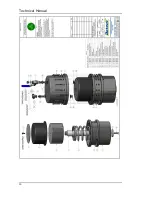
Page 30: ...Technical Manual 30 ...
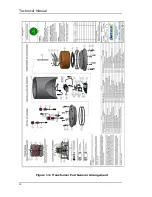
Page 32: ...Technical Manual 32 Figure 14 Transformer Pod General Arrangement ...
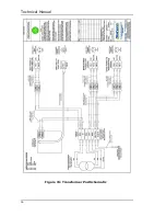
Page 36: ...Technical Manual 36 Figure 15 Transformer Pod Schematic ...
Page 39: ...Neptune 5000 Copyright Datem Limited 2014 39 Figure 16 Electronics Pod General Arrangement ...
Page 44: ...Technical Manual 44 Figure 19 Neptune 5000 Electronics Pod Wiring Schematic ...
Page 51: ...Neptune 5000 Copyright Datem Limited 2014 51 Figure 23 Inverter Pod General Arrangement ...
Page 52: ...Technical Manual 52 Figure 24 Inverter Pod Assembly ...
Page 55: ...Neptune 5000 Copyright Datem Limited 2014 55 Figure 25 Inverter Pod Wiring Schematic ...
Page 57: ...Neptune 5000 Copyright Datem Limited 2014 57 Figure 26 Inverter Function Settings ...
Page 62: ...Technical Manual 62 Figure 27 Thruster General Assembly ...
Page 63: ...Neptune 5000 Copyright Datem Limited 2014 63 Figure 28 Thruster Backplate and Driver Assembly ...
Page 64: ...Technical Manual 64 Figure 29 Thruster Drum and Cassette Assembly ...
Page 68: ...Technical Manual 68 ...
Page 70: ...Technical Manual 70 Figure 30 Thruster Straightener Assembly ...
Page 77: ...Neptune 5000 Copyright Datem Limited 2014 77 Figure 34 5cm2 Digital Cone Assembly ...
Page 78: ...Technical Manual 78 Figure 35 10cm2 Digital Cone Assembly ...
Page 90: ...Technical Manual 90 ...
Page 91: ...Neptune 5000 Copyright Datem Limited 2014 91 Figure 45 Encoder Parts Drawing ...
Page 95: ...Neptune 5000 Copyright Datem Limited 2014 95 ...
Page 102: ...Technical Manual 102 ...
Page 104: ...Technical Manual 104 ...
Page 105: ...Neptune 5000 Copyright Datem Limited 2014 105 ...
Page 106: ...Technical Manual 106 ...
Page 107: ...Neptune 5000 Copyright Datem Limited 2014 107 ...
Page 108: ...Technical Manual 108 ...
Page 110: ...Technical Manual 110 ...
Page 111: ...Neptune 5000 Copyright Datem Limited 2014 111 ...
Page 112: ...Technical Manual 112 ...
Page 113: ...Neptune 5000 Copyright Datem Limited 2014 113 ...
Page 115: ...Neptune 5000 Copyright Datem Limited 2014 115 ...
Page 116: ...Technical Manual 116 ...
Page 117: ...Neptune 5000 Copyright Datem Limited 2014 117 ...


