Neptune 5000
© Copyright Datem Limited 2014
23
prevent the potential for any fastenings friction welding together, all nuts and
bolts should be assembled using an anti-seize compound. Attention should be
taken to ensure that the correct washers and Nylock nuts are used in the
appropriate locations, to prevent frame failure during operation.
Umbilical Termination
In some situations it may be necessary to remake the umbilical termination,
due to cable shortening or replacement through damage. Whilst not supplied
by Datem, if the termination mounted on the umbilical is an open spelter
socket it can normally be re-used. To reuse the termination, cut the cable
close to the end of the socket, and drill out the centre. The remaining cast
Wirelock® can be removed with a small chisel and a hammer.
When remaking the termination, it is important to ensure that the steel wire
armour on the cable is not allowed to start unwinding when it is cut. With the
open socket slid over the cable, follow the instructions enclosed with the
Wirelock® kit for fitting. A sample instruction sheet for the Wirelock® kit can
be found in appendix A, but caution should be taken to ensure that the
Wirelock® supplied is the same product. Care should be taken to ensure that
the coaxial cable core of the umbilical exits the open socket in the centre, and
is not coated in any of the Wirelock® compound. Please refer to appendix B
for hazard information related to this operation.
NOTE:
It is recommended in addition to brooming the wire, to bend the end
15mm of every strand round on itself to form a hook shape.
Maintenance
Appropriate safe working practices should be followed to ensure
that all hazards are minimised.
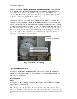
When the system is in operation, it should be washed down with clean, salt-
free water whenever it is returned to the deck of the ship. This will reduce
corrosion, and reveal any damage to the frame members. Particular attention
should be paid to the condition of the open socket fitted to the umbilical, and
all the lifting arrangement that connects it to the frame’s top plate. Any
damage, creepage, or fractures in any of these parts demands immediate
replacement before further use.
The electrical cables connecting the umbilical to the Power Pod should be
visually inspected regularly to ensure there are no chafes or cut in the
insulation. The connectors on all these cables should be tightly fitted with no
Summary of Contents for Neptune 5000
Page 1: ...Neptune 5000 Copyright Datem Limited 2014 1 Neptune 5000 Technical Manual ...
Page 14: ...Technical Manual 14 Figure 3 Topside Control Box Wiring Schematic ...
Page 15: ...Neptune 5000 Copyright Datem Limited 2014 15 Figure 4 Topside Control Box Wiring Layout ...
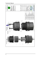
Page 30: ...Technical Manual 30 ...
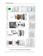
Page 32: ...Technical Manual 32 Figure 14 Transformer Pod General Arrangement ...
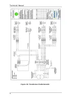
Page 36: ...Technical Manual 36 Figure 15 Transformer Pod Schematic ...
Page 39: ...Neptune 5000 Copyright Datem Limited 2014 39 Figure 16 Electronics Pod General Arrangement ...
Page 44: ...Technical Manual 44 Figure 19 Neptune 5000 Electronics Pod Wiring Schematic ...
Page 51: ...Neptune 5000 Copyright Datem Limited 2014 51 Figure 23 Inverter Pod General Arrangement ...
Page 52: ...Technical Manual 52 Figure 24 Inverter Pod Assembly ...
Page 55: ...Neptune 5000 Copyright Datem Limited 2014 55 Figure 25 Inverter Pod Wiring Schematic ...
Page 57: ...Neptune 5000 Copyright Datem Limited 2014 57 Figure 26 Inverter Function Settings ...
Page 62: ...Technical Manual 62 Figure 27 Thruster General Assembly ...
Page 63: ...Neptune 5000 Copyright Datem Limited 2014 63 Figure 28 Thruster Backplate and Driver Assembly ...
Page 64: ...Technical Manual 64 Figure 29 Thruster Drum and Cassette Assembly ...
Page 68: ...Technical Manual 68 ...
Page 70: ...Technical Manual 70 Figure 30 Thruster Straightener Assembly ...
Page 77: ...Neptune 5000 Copyright Datem Limited 2014 77 Figure 34 5cm2 Digital Cone Assembly ...
Page 78: ...Technical Manual 78 Figure 35 10cm2 Digital Cone Assembly ...
Page 90: ...Technical Manual 90 ...
Page 91: ...Neptune 5000 Copyright Datem Limited 2014 91 Figure 45 Encoder Parts Drawing ...
Page 95: ...Neptune 5000 Copyright Datem Limited 2014 95 ...
Page 102: ...Technical Manual 102 ...
Page 104: ...Technical Manual 104 ...
Page 105: ...Neptune 5000 Copyright Datem Limited 2014 105 ...
Page 106: ...Technical Manual 106 ...
Page 107: ...Neptune 5000 Copyright Datem Limited 2014 107 ...
Page 108: ...Technical Manual 108 ...
Page 110: ...Technical Manual 110 ...
Page 111: ...Neptune 5000 Copyright Datem Limited 2014 111 ...
Page 112: ...Technical Manual 112 ...
Page 113: ...Neptune 5000 Copyright Datem Limited 2014 113 ...
Page 115: ...Neptune 5000 Copyright Datem Limited 2014 115 ...
Page 116: ...Technical Manual 116 ...
Page 117: ...Neptune 5000 Copyright Datem Limited 2014 117 ...


