Technical Manual
84
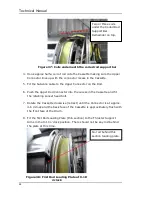
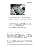
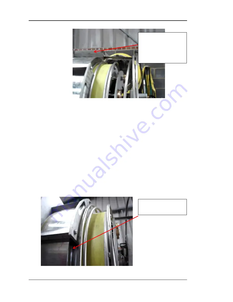
Figure 37: Coils underneath the coiled rod support bar
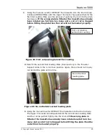
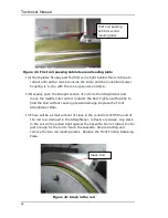
Figure 38: First Rod Loading Plate at 9-10
o’clock
4.
Hook approx half a coil of rod onto the Cassette making sure the Upper
Connector lines up with the connector recess in the Cassette.
5.
Fit the Subconn cable to the Upper Connector on the Rod.
6.
Push the Upper Rod Connector into the recess in the Cassette and fit
the retaining socket head bolt.
7.
Rotate the Cassette clockwise (retract) until the Connector is at approx.
4-6 o’clock and the back face of the Cassette is approximately flush with
the front face of the Drum.
8.
Fit the first Rod Loading Plate (thin section) to the Thruster Support
Arms in the 9-10 o’clock position. There should not be any rod behind
the plate at this time.
Two or three coils
under the Coiled Rod
Support Bar.
Remainder on top.
No rod behind this
section loading plate.
Summary of Contents for Neptune 5000
Page 1: ...Neptune 5000 Copyright Datem Limited 2014 1 Neptune 5000 Technical Manual ...
Page 14: ...Technical Manual 14 Figure 3 Topside Control Box Wiring Schematic ...
Page 15: ...Neptune 5000 Copyright Datem Limited 2014 15 Figure 4 Topside Control Box Wiring Layout ...
Page 30: ...Technical Manual 30 ...
Page 32: ...Technical Manual 32 Figure 14 Transformer Pod General Arrangement ...
Page 36: ...Technical Manual 36 Figure 15 Transformer Pod Schematic ...
Page 39: ...Neptune 5000 Copyright Datem Limited 2014 39 Figure 16 Electronics Pod General Arrangement ...
Page 44: ...Technical Manual 44 Figure 19 Neptune 5000 Electronics Pod Wiring Schematic ...
Page 51: ...Neptune 5000 Copyright Datem Limited 2014 51 Figure 23 Inverter Pod General Arrangement ...
Page 52: ...Technical Manual 52 Figure 24 Inverter Pod Assembly ...
Page 55: ...Neptune 5000 Copyright Datem Limited 2014 55 Figure 25 Inverter Pod Wiring Schematic ...
Page 57: ...Neptune 5000 Copyright Datem Limited 2014 57 Figure 26 Inverter Function Settings ...
Page 62: ...Technical Manual 62 Figure 27 Thruster General Assembly ...
Page 63: ...Neptune 5000 Copyright Datem Limited 2014 63 Figure 28 Thruster Backplate and Driver Assembly ...
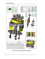
Page 64: ...Technical Manual 64 Figure 29 Thruster Drum and Cassette Assembly ...
Page 68: ...Technical Manual 68 ...
Page 70: ...Technical Manual 70 Figure 30 Thruster Straightener Assembly ...
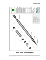
Page 77: ...Neptune 5000 Copyright Datem Limited 2014 77 Figure 34 5cm2 Digital Cone Assembly ...
Page 78: ...Technical Manual 78 Figure 35 10cm2 Digital Cone Assembly ...
Page 90: ...Technical Manual 90 ...
Page 91: ...Neptune 5000 Copyright Datem Limited 2014 91 Figure 45 Encoder Parts Drawing ...
Page 95: ...Neptune 5000 Copyright Datem Limited 2014 95 ...
Page 102: ...Technical Manual 102 ...
Page 104: ...Technical Manual 104 ...
Page 105: ...Neptune 5000 Copyright Datem Limited 2014 105 ...
Page 106: ...Technical Manual 106 ...
Page 107: ...Neptune 5000 Copyright Datem Limited 2014 107 ...
Page 108: ...Technical Manual 108 ...
Page 110: ...Technical Manual 110 ...
Page 111: ...Neptune 5000 Copyright Datem Limited 2014 111 ...
Page 112: ...Technical Manual 112 ...
Page 113: ...Neptune 5000 Copyright Datem Limited 2014 113 ...
Page 115: ...Neptune 5000 Copyright Datem Limited 2014 115 ...
Page 116: ...Technical Manual 116 ...
Page 117: ...Neptune 5000 Copyright Datem Limited 2014 117 ...

