background image

Technical Manual 

96


Operational Information 

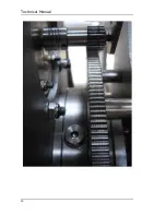
There are two very important criteria that must be observed when working 

with the cone-up sensor.  

1.


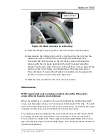
The magnetic flux unit and the sensor must be correctly orientated 
to ensure correct operation. The two large spots on the magnetic 

flux unit must be orientated vertically (in line with the cone-rod). On 

the back of the sensor is a small location-marking slot. This must be 
positioned in line with the magnetic flux unit’s black markers.  

2.


The distance between the magnetic flux unit and the sensor is very 

critical.  It must be between approximately 30mm, symmetrically 
positioned about the cone-rod. 

Maintenance 

NOTE:


Appropriate safe working practices should be followed to ensure that 
all hazards are minimised. 

When the system is in operation, the cone-up sensor should be washed down 

with clean, salt-free water whenever it is returned to the deck of the ship. This 

will reduce corrosion, and enable thorough inspection of all the main housings, 
connector, and connecting cable. 

It is good working practice to regularly check all fastenings to ensure they are 

present, tight, and there is no damage to them or the items they are fitted to. 
Any damaged fastenings should be replaced immediately. 

The positioning and orientation of the sensors should be checked on a regular 

basis. It is also necessary to ensure the lock nuts are tight. 

The electrical cable connected to the cone-up sensor should be visually 

inspected to ensure there are no chafes or cuts in the insulation. The 

connectors on both ends of the cable should be tightly fitted with no face gap, 
and the lock-rings should be finger-tight. Any damaged cables or lock-rings 

should be replaced immediately. 


Summary of Contents for Neptune 5000

Page 1: ...Neptune 5000 Copyright Datem Limited 2014 1 Neptune 5000 Technical Manual ...

Page 2: ...d to MS MS Multiple 2 16 03 10 Electronics Update MS All 3 22 07 11 Issued to MS MS All 4 10 12 12 Client Release AB All 5 19 03 13 Client Release MS All 6 05 02 14 Client Release MS All 7 22 10 14 Client Release AB This document is the property of DATEM and should not be disclosed without prior written consent ...

Page 3: ...e 9 Software 10 Description 10 Specification 10 Operational Information 10 Maintenance 10 Trouble Shooting 11 Topside Control Box 12 Description 12 Specification 13 Electrical Installation 13 Topside Power Supply PCB 16 Topside Telemetry Board 18 LCD Displays 20 Maintenance 21 Frame Assembly 22 Description 22 Specification 22 Assembly 22 Maintenance 23 ...

Page 4: ...on 31 Specification 33 Assembly 33 Electrical Installation 35 Operational Information 37 Maintenance 37 Electronics Pod Assembly 38 Description 38 Specification 40 Subsea Power Supply PCB 41 Subsea Connector PCB 42 Subsea Microcontroller Board 45 Subsea Telemetry Board 47 Inverter Pod Assembly 49 Description 49 Specification 50 Assembly 51 Motor Gearbox Assembly 59 ...

Page 5: ...Assembly 61 Description 61 Specification 61 Assembly 61 Maintenance 65 Chassis 65 Mechanism 65 Bearing Housing 67 Assembly 67 Straightener 68 Slip ring 73 Cone 75 Description 75 Specification 76 Assembly 76 Operational Information 79 Maintenance 80 Cone Rod Assembly 81 Description 81 Specification 81 Assembly 81 ...

Page 6: ...9 Assembly 89 Operational information 89 Maintenance 91 Cone Up Sensor Assembly 93 Description 93 Specification 93 Assembly 94 Operational Information 96 Maintenance 96 Altimeter Assembly 97 Description 97 Specification 97 Assembly 97 Operational information 97 Maintenance 98 Fault Finding 99 Tools and Equipment 100 Recommended Mechanical Tool Kit 100 ...

Page 7: ...ed Specialist Tools 100 Appendix A 101 Sample instructions for the wirelock kit 101 Appendix B 103 Material safety data sheet for wirelock kit 103 Appendix C 109 Material safety data sheets for loctite 242 threadlocker 109 Appendix D 114 Material safety data sheets for HM10 hydraulic oil 114 ...

Page 8: ...the Datem Digital Cone to provide accurate in situ soil data from the transition zone to water depths up to 3000 metres and will allow seabed penetration of up to 20 metres The system consists of the subsea thruster and frame illustrated in figure 1 a topside control box for powering the system and providing computer connection and Datem s dedicated PC software for control and data acquisition The...

Page 9: ...Data Rate 1 Hz Topside Software Windows 7 Vista XP Compatible General System Maintenance When the system is in operation it should be washed down with clean salt free water whenever it is returned to the deck of the ship This will reduce corrosion and reveal any damage to the frame pods compensator thruster or cables The electrical cables connected to the sensors pods and auxiliary equipment shoul...

Page 10: ...e software is to ensure that the hard drive has plenty of space and that running processes on the computer are kept to a minimum thus allowing the software to run at maximum speed with no delay Removing any unwanted applications can be achieved by navigating to the computers control panel and then selecting Add Remove Programs It is also good practice to regularly run the Scandisk software recomme...

Page 11: ... solution to such problems is to re install the Neptune 5000 software using the installation CD ROM provided If communication cannot be established when running the software a mis configured communication port could be the cause Ensure that the Ethernet communication IP addresses are assigned correctly IP Address 192 168 0 55 192 168 0 255 between 55 and 255 Subnet Mask 255 255 255 0 Default Gatew...

Page 12: ...ed push button switches Three cables are supplied for use with the Topside Control Box Mains Supply PC Ethernet and High Voltage Deck Umbilical Only these supplied cables should be used with the system Always ensure that all the cables are fitted correctly before supplying power to the Topside Control Box When power is supplied the MAINS POWER red push button switch will illuminate indicating that...

Page 13: ...Umbilical HV voltage Main Fuse rating MCB 16A Type B WARNING Appropriate safe working practices should be followed to ensure that all hazards are minimised It should be noted that although the power switches may be turned off there are still live terminals inside the box Electrical Installation Wiring schematic diagrams of the Topside Control Box are illustrated on the following pages It should be...

Page 14: ...Technical Manual 14 Figure 3 Topside Control Box Wiring Schematic ...

Page 15: ...Neptune 5000 Copyright Datem Limited 2014 15 Figure 4 Topside Control Box Wiring Layout ...

Page 16: ...or indication on the voltmeter and ammeter displays Topside Power Supply Circuit Description The Topside Power Supply Board has the following plug connections PL1 Supply input to the Current Sensing Circuit PL2 Supply output from the Current Sensing Circuit PL3 Supply input to the High Voltage Sensing Circuit PL4 Supply Output from the High Voltage Sensing Circuit PL5 Sensor output to Voltmeter Di...

Page 17: ...mmeter display The High Voltage output from TXF1 connects to the Topside Power Supply Board on connector PL3 It then passes through the high voltage sensing circuitry and then exits the board on PL4 The high voltage sensing circuit comprises a divider network isolating transformer TR1 and a bridge rectifier The voltmeter signals are output on PL5 and PL7 provides the 5Vdc power The Topside Power S...

Page 18: ...Coupler PCB located in the Subsea Transformer Pod The telemetry system gives a transparent full duplex serial link between the Topside PC and the Subsea Microcontroller capable of transferring data at 19200 baud The digital information is superimposed on the high voltage CPT supply by means of frequency shift keying FSK The Topside Telemetry Board transmits using a different carrier frequency than...

Page 19: ...ut not to the subsea CPT the Topside Telemetry PCB will repeat its tuning sequence until the Subsea Telemetry Board has been powered up Once communication has been established each board continuously transmits a handshake message while checking for received handshake messages This process is independent of any communications between the Topside PC and the Subsea Microcontroller A breakdown in tele...

Page 20: ... and received After a successful tuning sequence the Topside Telemetry Board stores its tuning results together with those obtained from the Subsea Telemetry Board These results are displayed on the Engineering Screen of the Neptune 5000 program Level is a code related to the receiving circuit threshold voltage Quality is a value corresponding to the number of consecutive valid tuning strings rece...

Page 21: ...sed It should be noted that although the power switches may be turned off there are still live terminals inside the box The electrical cables connected to the Topside control box should be visually inspected regularly to ensure there are no chafes or cuts in the insulation The connectors on both ends of the cables should be tightly fitted with no face gap and the lock rings should be finger tight ...

Page 22: ...ith some degree of protection against low energy impact This part of the frame is completely constructed from a marine grade of stainless steel using predominantly tubular structures for maximum strength To protect the dissimilar metals used in the construction of the frames and base sacrificial anodes are mounted to the base These should corrode at an accelerated rate in order to protect the main...

Page 23: ...can be found in appendix A but caution should be taken to ensure that the Wirelock supplied is the same product Care should be taken to ensure that the coaxial cable core of the umbilical exits the open socket in the centre and is not coated in any of the Wirelock compound Please refer to appendix B for hazard information related to this operation NOTE It is recommended in addition to brooming the...

Page 24: ...tified the parts they were removed from should be inspected to ensure there is no damage to them Any damaged fastenings should be replaced immediately Frame members showing any sign of damage should be assessed for their structural integrity and repaired or replaced if the damage constitutes an exaggerated degradation in the safe operation of the system Be sure to use anti seize compound on all fr...

Page 25: ... 10 or similar hydraulic oil The internal pressure is proportional to the depth of water the system is operating in and will always be approximately 0 5 bar higher than the surrounding pressure By operating in this manner any failures in the seals of the system will result in oil leaving the pressurised system as opposed to water entering the system Observation of the diaphragm pressure indicator ...

Page 26: ...hence removal of any fittings on the compensator or motor without following the correct depressurisation procedure will result in rapid release of high pressure liquid It is highly recommended to wear personal protective equipment during work on the compensator and motor in particular overalls and safety glasses Appropriate precautions should be taken to avoid all contact with the oil in the press...

Page 27: ... white coloured marker protruding from the bottom of the compensator is barely visible and the oil has ceased to flow from the assembly With the pressure released any work carried out on the compensator or motor requires the remaining oil to be drained from the appropriate item Pressurisation It is highly recommended to wear personal protective equipment during the pressurisation process in partic...

Page 28: ...fied by approximately 75mm of indicator visible At this point the hydraulic valve should be closed the pressure pump hose removed and the plug replaced on the valve Finally check all the hydraulic fittings to ensure they are all tight Any further spilt oil should be cleaned up immediately to prevent the risk of slipping or environmental contamination Operational Information Where the compensator i...

Page 29: ...egularly to ensure they are all tight By simply looking at the white marker protruding from the bottom of the compensator it is possible to determine whether there has been any loss of oil during operation There should be approximately 75mm of marker visible when the system is correctly pressurised It is good working practice to regularly check all fastenings to ensure they are present tight and t...

Page 30: ...Technical Manual 30 ...

Page 31: ...The secondary windings of the transformer are connected to a terminal block Link wires on the terminal block allows for voltage selection from the different secondary windings Once the system is commissioned on the umbilical it should not be necessary to make any changes to this voltage selection The power from the secondary winding is used to power the Electronics Pod and the Inverter Pod This po...

Page 32: ...Technical Manual 32 Figure 14 Transformer Pod General Arrangement ...

Page 33: ...1 Firstly ensure the power is removed from the system and appropriate action is taken to prevent accidental energisation 2 Remove all the cables from the pod s connectors 3 Remove the nuts on the back of the U shaped clamps round the vessel of the pod 4 Remove the clamps from the vessel 5 Move the pod in from the side so that it is not under the side bars of the frame 6 Check that all the top cap ...

Page 34: ... vessel in case of lifting apparatus failure leaving sufficient space for access by hand 7 Disconnect all the in line cable connectors that attach the top cap to the internal equipment 8 Slowly remove the cap ensuring that no cables have snagged and place upside down on a suitable Topside to prevent connector damage 9 If the top cap is removed with the pod outside place an appropriate blanking pla...

Page 35: ...cking holes and systematically turn them jacking the entire end cap out of the vessel 5 Fit a lifting eye into the central M12 tapped hole and attach an appropriate hoist 6 Slowly hoist the end cap and transformer assembly 7 Place the end cap and transformer assembly to one side to avoid risk of lifting apparatus failure taking care to rest the cap on its base not on the transformer 8 The transfor...

Page 36: ...Technical Manual 36 Figure 15 Transformer Pod Schematic ...

Page 37: ... inspection of all the main housing connectors and connecting cables It is good working practice to regularly check all clamp fastenings to ensure they are present tight and there is no damage to them or the items they are fitted to Any damaged fastenings should be replaced immediately The electrical cables connected to the Transformer Pod should be visually inspected to ensure there are no chafes...

Page 38: ...CB that provides power for the Datem Digital Cone Data is passed to the Telemetry PCB inside the Electronics Pod via a co axial connector from the Power Pod The data is de coupled from the high voltage AC supply in the Transformer Pod by the Data Coupler PCB prior to sending to the Electronics Pod A Connector PCB inside the Electronics Pod provides the means of interconnecting the Telemetry Board ...

Page 39: ...Neptune 5000 Copyright Datem Limited 2014 39 Figure 16 Electronics Pod General Arrangement ...

Page 40: ...d take place in a dry workshop In many cases it is acceptable to leave the pressure vessel on the frame and simply remove the end cap and chassis assembly to the workshop The vessel clamps will need removing as the pressure vessel will need to be moved away from the edge of the frame to allow the end cap and chassis assembly to be lifted clear To remove the end cap and chassis assembly 1 Ensure th...

Page 41: ...ion The subsea transformer secondary output is connected to the mains input screw terminals on PL3 The voltage on these terminals will be at mains potential 240Vac The live fed passes though board protection fuse FS1 rated at 5 amps acting as a link and then through FS3 rated at 2 amps The output from FS3 feds a mains input filter A Protective cover is fitted over this part of the board Two AC to ...

Page 42: ...er and the Subsea Telemetry PCB Circuit Description Power is supplied to the board on connectors PL6 Telemetry power and PL7 Controller Cone The Altimeters are connected to PL3 Optional and communicate with the Subsea Microcontroller on a RS232 serial link The penetration and cone up sensors are connected to PL4 The Hydrostatic sensor is connected to PL2 The Cone is connected to PL1 and is wired f...

Page 43: ... Telemetry PCB using on board connectors The Subsea Microcontroller board simply plugs onto the Connector PCB using plugs PL9 PL10 PL11 and PL12 Specification Supply Input Controller Cone 12VDC 15VDC Telemetry 15VDC Electrical Installation A wiring schematic diagram of the Electronics pod is shown in Figure 19 ...

Page 44: ...Technical Manual 44 Figure 19 Neptune 5000 Electronics Pod Wiring Schematic ...

Page 45: ...als 4 Inverter Pod status control Inverter Pod Voltage Current Temperature Humidity and Control 5 Penetration distance monitoring from Encoder 6 Cone position from Cone Up Sensor 7 Onboard temperature and humidity sensing 8 Onboard Frame Tilt Sensing or external Frame Tilt monitoring 9 Hydrostatic Pressure monitoring if pressure sensor fitted 10 10m and 100m Altimeter monitoring Circuit Descriptio...

Page 46: ...Bytes Clock Speed 7 3728 MHz LED Indicators The Microcontroller has 20 LEDS situated on the PCB to indicate correct board system operation Error Reference source not found below shows the Microcontroller Board Layout The on board LEDs are designated as follows LED NUMBER LED COLOUR LED LABEL LED DESIGNATION 1 GREEN 12V B 12V Board Supply 2 GREEN 5V B Regulated 5V Board 3 GREEN 15V C 15V Cone Suppl...

Page 47: ...Motor Speed varying with brightness Neptune 3000 only 19 WHITE MOTOR FWD Motor Forward signal Neptune 3000 only 20 WHITE MOTOR REV Motor Reverse signal Neptune 3000 only Subsea Telemetry Board Overview The Subsea Telemetry Board illustrated in Error Reference source not found works with the Topside Telemetry Board and coupling circuitry located on the Subsea Power Supply Board and the Topside Powe...

Page 48: ...here are no hardware faults During tuning the Tx1 LED is illuminated while the Rx1 LED turns on and off at about 1 second intervals Once two way communication has been established both Tx1 and Rx1 will blink very rapidly at about equal intensity showing that handshake messages are being transmitted and received Maintenance NOTE Appropriate safe working practices should be followed to ensure that a...

Page 49: ... sequential catastrophic failure Inverter Pod Assembly Description The Inverter Pod is manufactured from low carbon grade 316 stainless steel and is dry sealed at atmospheric pressure There are three Subconn connectors on the top cap of the pod for interconnection to the system The mains power comes straight from the power terminal block in the Transformer Pod and the RS485 control comes from the ...

Page 50: ...he motor parameters 1 Inverter mains input voltage 2 Inverter input current 3 Pod temperature and humidity measurement The general arrangement and connector details for this pod can be seen on the following pages Specification Dimensions approx 484mm long x 247mm diameter Weight in Air approx 70 Kg Maximum Operating Pressure 300 Bar Voltage Supply 240Vac 10 Output characteristics 0 220Vac Variable...

Page 51: ...Neptune 5000 Copyright Datem Limited 2014 51 Figure 23 Inverter Pod General Arrangement ...

Page 52: ...Technical Manual 52 Figure 24 Inverter Pod Assembly ...

Page 53: ...nt of the inverter or filter require full removal of the pod to a dry workshop To remove the pod from the frame 1 Firstly ensure the power is removed from the system and appropriate action is taken to prevent accidental energisation 2 Remove all the cables from the pod s connectors 3 Remove the nuts from the vessel clamps and remove the clamps from the vessel 4 Move the pod in from the side so tha...

Page 54: ...ot be left like this outside for very long due to the high risk of moisture ingress Pot Top Cap Refitting Refitting the top cap is simply the reverse process of removal but special care should be taken with ensuring the o rings are in good condition and lightly lubricated with silicone grease Pod Disassembly It is not considered necessary to disassemble the inverter pod for the majority of work un...

Page 55: ...Neptune 5000 Copyright Datem Limited 2014 55 Figure 25 Inverter Pod Wiring Schematic ...

Page 56: ...ains cabling and connectors that are at a potential of 240Vac when power is connector to the unit To check the inverter settings are correct use the supply documentation provided with the unit The data provided in Error Reference source not found overleaf lists the function settings that should be present in the inverter drive unit during normal operation Operational information Where the pod is d...

Page 57: ...Neptune 5000 Copyright Datem Limited 2014 57 Figure 26 Inverter Function Settings ...

Page 58: ...g connectors and connecting cables It is good working practice to regularly check all clamp fastenings to ensure they are present tight and there is no damage to them or the items they are fitted to Any damaged fastenings should be replaced immediately The electrical cable connected to the inverter pod should be visually inspected to ensure there are no chafes or cut in the insulation The connecto...

Page 59: ...led 4 pole a c induction motor directly attached to a right angle worm drive and a 5 stage epicyclic reduction gearbox directly fastened to the back plate of the thruster The gearbox output shaft rotary speed provides penetration of 2cm per second This reduction gearbox also provides the necessary torque to give a maximum push of 35kN Specification Motor Type 3 Phase induction Motor Rating Nom 240...

Page 60: ...amage to them or the items they are fitted to Any damaged fastenings should be replaced immediately The electrical cable connected to the motor should be visually inspected to ensure there are no chafes or cut in the insulation The connectors on both ends of the cable should be tightly fitted with no face gap and the lock rings should be finger tight Any damaged cables or lock rings should be repl...

Page 61: ... Penetration Force 35kN Penetration Speed 2cm s 10 Rod Length Capacity 20m Mass 2300 Kg Maximum Operating Pressure 300 Bar Assembly A series of exploded views of the thruster are illustrated on the following pages These drawings provide a representation of the main parts that make up the assembly and the way in which they fit together Some parts of the thruster such as penetration encoder are furt...

Page 62: ...Technical Manual 62 Figure 27 Thruster General Assembly ...

Page 63: ...Neptune 5000 Copyright Datem Limited 2014 63 Figure 28 Thruster Backplate and Driver Assembly ...

Page 64: ...Technical Manual 64 Figure 29 Thruster Drum and Cassette Assembly ...

Page 65: ...uring operation It is manufactured from thick marine grade stainless steel plate with bolted construction to minimise any problems generally associated with heat based assembly principles The chassis consists of a back plate that has gussets bolted to it that provide the mounting arrangement for the chassis to a sub frame A mounting shelf at the rear is provided for the motor gearbox assembly The ...

Page 66: ...ion unit all connected together by a length of hydraulic hose This unit is sealed by the manufacturers and should not be tampered with Maintenance When the unit is returned to the deck after use the five lead screw drive pinions and the lead screws should be washed down with clean water to remove any sediment or debris lodged inside the teeth of the gears threads A general inspection and check sho...

Page 67: ...e found on the following page This drawing provides a representation of the main parts that make up the assembly and the way in which they fit together When ordering any replacement parts please quote the assembly drawing number revision and title followed by the item number and description of the part you wish to order Maintenance Check for any oil leaks before and after system use Any excess air...

Page 68: ...Technical Manual 68 ...

Page 69: ...blocks to remove any debris from the cone rod before it enters the roller arrangement Below the scraper blocks is the cone up sensor which provides the electronics with the relevant signals to identify when the cone extension rod is located in the upper most position Assembly An exploded view of the straightener is illustrated in Drawing 1127 01 ASS which can be found on the following page This dr...

Page 70: ...Technical Manual 70 Figure 30 Thruster Straightener Assembly ...

Page 71: ...ove and retighten the bolts by hand to prevent accidental movement 6 The rod can now be pulled out of the gap between the rollers When refitting a cone rod the above procedure can be followed in reverse order but before the final operation of tightening the lock nuts the straightener must be correctly adjusted as discussed below Straightener Adjustment Whenever a new rod is fitted it is necessary ...

Page 72: ...y from under the thruster retract the rod until the cone is back in the cone up sensor while loosening the middle roller by 1 8 of a turn Remember that using the manual inverter requires close observation to stop the cone in the correct position Perform another push without adjusting the roller and return to operation 4 observing the angle 7 With the straightener finally set up satisfactorily tigh...

Page 73: ...on the front support pedestal and a hydraulic hose connecting the two items Specification Number of circuits 6 Voltage rating 240Vac Current rating 2A Oil From Compensator Assembly Assembly The slip ring assembly is below in Drawing 1534 01 GA This drawing provides a representation of the main parts that make up the assembly and the way in which they fit together There are no user serviceable part...

Page 74: ...tenance When mobilising the system or fitting a new slip ring that has not been in use for an extended period of time it may be necessary to rotate the unit for 1 to 2 minutes to ensure that any residue on the rings is removed ...

Page 75: ...onical angle from a vertical datum point An optional pore pressure element can be fitted in the end of the cone to sense the pressure differential generated as the cone moves deeper into the seabed All Datem cones contain sophisticated electronic systems that fulfil precision power stabilisation and signal conditioning functionality The main advantage of using a digital output is that system noise...

Page 76: ...ws of the 5cm2 and 10cm2 cones are illustrated below These drawings provide a representation of the main parts that make up the assembly and the way in which they fit together The assembly drawing illustrates the only parts of the cone that are field serviceable Although some degree of more extensive servicing is possible on cones sustaining field damage it s recommended to return the cone to the ...

Page 77: ...Neptune 5000 Copyright Datem Limited 2014 77 Figure 34 5cm2 Digital Cone Assembly ...

Page 78: ...Technical Manual 78 Figure 35 10cm2 Digital Cone Assembly ...

Page 79: ...g to pull the cable out too far can damage the cable 4 Refit the cone s connector cover and place it in a transit case for safety Cone Fitting 1 Remove the cone from the transit case making note of the serial number on the end of the cone body This is important to ensure that when the system is operated the automatic cone selection function can be verified 2 Remove the connector cover and store in...

Page 80: ...cone rod The condition of the tip and sleeve should also be identified as a badly worn tip and or sleeve can cause a severe degradation in the quality of data obtained Spare cones should be carried at all times so that an alternative cone can be fitted while cones with worn tips and sleeves are being serviced There is a viewing window in the support block to allow the dirt seals at each end of the...

Page 81: ...ne rod has a stainless steel termination block fitted with an 8 pin male bulkhead Subconn The termination block is secured to the thruster cassette to transfer the driving force The cone end of the rod terminates with a cone coupling assembly that fastens on to the cone via a crossover coupling and provides a watertight connection via o ring seals Internal wires in the cone rod are terminated in a...

Page 82: ...ont plate to enable the rod to be pulled from the roller assembly 3 Remove both rod guides from the front friction retaining plate 4 Remove the front friction retaining plate and lay it forwards around the pedestal that houses the front bearing and encoder 5 Using the manual inverter rotate the cassette anticlockwise THRUST to feed the rod slowly out of the cassette 6 Continue to THRUST the rod un...

Page 83: ...cedure then the cassette should be in the correct position to fit another rod This should mean that the Upper Connector Recess on the Cassette is approximately between the 2 o clock and 3 o clock positions when looking at the cassette from the front Take care not to rotate the cassette whilst the rod is not loaded 2 Attach the Coiled Rod Support bar used for holding the rods during loading to the ...

Page 84: ...r Rod Connector into the recess in the Cassette and fit the retaining socket head bolt 7 Rotate the Cassette clockwise retract until the Connector is at approx 4 6 o clock and the back face of the Cassette is approximately flush with the front face of the Drum 8 Fit the first Rod Loading Plate thin section to the Thruster Support Arms in the 9 10 o clock position There should not be any rod behind...

Page 85: ...apped before fitting the plate then the rod will not be loaded properly 10 Now fit the second Rod Loading Plate thick section to the Thruster Support Arms in the 3 4 o clock position Again there should not be any rod behind the plate at this time 11 Using the manual inverter RETRACT the Cassette into the Drum slowly The Upper Connector should pass behind the second Rod Loading Plate and the rod be...

Page 86: ...nd move the middle roller until it contacts the Rod Tighten sufficiently to hold the Rod without causing physical damage Replace the Front Straightener Plate 14 There will be a small amount of slack in the coiled rod With the end of the rod now clamped in the Straightener retract very slowly Any slack in the coil will be pulled tight against the Cassette Do not retract too far just enough for the ...

Page 87: ...the rod in the center of the base plate hole 17 Refit the cone as stated in the cone removal section Maintenance NOTE Appropriate safe working practices should be followed to ensure that all hazards are minimised When the system is in operation the cone rod should be washed down with clean salt free water whenever it is returned to the deck of the ship This will reduce corrosion and abrasion to th...

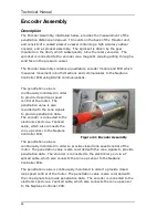
Page 88: ...monitored in order to provide closed loop speed control of the motor The penetration value is also recorded with the cone signals to provide penetration data The encoder is connected to the electronics pod via a Y spliced cable which also connects the cone up sensor to the Neptune Controller PCB The penetration value is continuously monitored in order to provide closed loop speed control of the mo...

Page 89: ...rts please quote the assembly drawing number revision and title followed by the item number and description of the part you wish to order Operational information When working on the encoder it is important to ensure that the operation tolerances are correct The face gap between the magnetic couplings and the faces they operate through must be 1mm 0 2mm This maintains a strong magnetic linkage betw...

Page 90: ...Technical Manual 90 ...

Page 91: ...Neptune 5000 Copyright Datem Limited 2014 91 Figure 45 Encoder Parts Drawing ...

Page 92: ... to regularly check all fastenings to ensure they are present tight and there is no damage to them or the items they are fitted to Any damaged fastenings should be replaced immediately The electrical cable connected to the encoder should be visually inspected to ensure there are no chafes or cuts in the insulation The connectors on both ends of the cable should be tightly fitted with no face gap a...

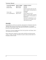
Page 93: ...es a magnetic flux which when set up correctly activates a magnetic flux sensor in the sensor housing The sensor relies on the use of materials in the cone rod with specific qualities The main rod material is none magnetic so when the cone is out the magnetic flux activates the sensor device The cone coupling is manufactured from a magnetic grade of stainless steel which blocks the magnetic flux f...

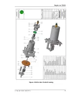
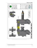
Page 94: ...gnment occurs during job only resolution is to use manual inverter Assembly An exploded view of the cone up sensor arrangement is illustrated in Drawing 1686 03b ASS which can be found on the following page This drawing provides a representation of the main parts that make up the assembly and the way in which they fit together There are no user serviceable parts in the cone up sensor unit Please r...

Page 95: ...Neptune 5000 Copyright Datem Limited 2014 95 ...

Page 96: ...ised When the system is in operation the cone up sensor should be washed down with clean salt free water whenever it is returned to the deck of the ship This will reduce corrosion and enable thorough inspection of all the main housings connector and connecting cable It is good working practice to regularly check all fastenings to ensure they are present tight and there is no damage to them or the ...

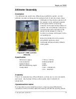
Page 97: ...seabed in order to monitor any sinkage with respect to the surrounding soil Data is transmitted from the sensors using RS232 protocols when individually addressed under software interrogation Specification Dimensions approx 170mm x 47mm Communication Addressed RS232 Supply Voltage 12Vdc Maximum Operating Depth 4000m Configuration 100m 200kHz 20 10m 500kHz 6 Assembly There is no exploded view of th...

Page 98: ...salt free water whenever it is returned to the deck of the ship This will reduce corrosion and enable thorough inspection of the main sensor housings connectors and connecting cables It is good working practice to regularly check all fastenings to ensure they are present tight and there is no damage to them or the items they are fitted to Any damaged fastenings should be replaced immediately The e...

Page 99: ...tuations When seeking advice it is necessary to provide the following information 1 Location 2 Details relating to the means of immediate Contact 3 Nature of problem 4 Any attempted resolution 5 Operational parameters 6 Cone used 7 System parameters Software versions etc 8 Any additional information considered to be relevant This correspondence should be through any of the following means e mail t...

Page 100: ... Screwdriver set VDE approved Allen Keys metric 1 5mm 3mm 4mm 5mm 6mm 8mm Long nose pliers VDE approved Cutters VDE approved Hammer Box Joint Pliers Recommended Electronics Tool Kit Anti static earth straps c w wristbands and termination Digital Multi meter Digital Scope meter Recommended Specialist Tools Digital Cone 25m 28mm C spanner Oil system pressurisation pump Manual Inverter ...

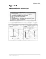
Page 101: ...Neptune 5000 Copyright Datem Limited 2014 101 Appendix A Sample instructions for the wirelock kit ...

Page 102: ...Technical Manual 102 ...

Page 103: ...pyright Datem Limited 2014 103 Appendix B Material safety data sheet for wirelock kit This information covers all the requirements of the Health and Safety at Work Act 1974 Section 6 C O S H H and C H I P regulations ...

Page 104: ...Technical Manual 104 ...

Page 105: ...Neptune 5000 Copyright Datem Limited 2014 105 ...

Page 106: ...Technical Manual 106 ...

Page 107: ...Neptune 5000 Copyright Datem Limited 2014 107 ...

Page 108: ...Technical Manual 108 ...

Page 109: ...t Datem Limited 2014 109 Appendix C Material safety data sheets for loctite 242 threadlocker This information covers all the requirements of the Health and Safety at Work Act 1974 Section 6 C O S H H and C H I P regulations ...

Page 110: ...Technical Manual 110 ...

Page 111: ...Neptune 5000 Copyright Datem Limited 2014 111 ...

Page 112: ...Technical Manual 112 ...

Page 113: ...Neptune 5000 Copyright Datem Limited 2014 113 ...

Page 114: ...cal Manual 114 Appendix D Material safety data sheets for HM10 hydraulic oil This information covers all the requirements of the Health and Safety at Work Act 1974 Section 6 C O S H H and C H I P regulations ...

Page 115: ...Neptune 5000 Copyright Datem Limited 2014 115 ...

Page 116: ...Technical Manual 116 ...

Page 117: ...Neptune 5000 Copyright Datem Limited 2014 117 ...

Page 118: ... With more than 30 seabed systems worldwide Datem is one of the major manufacturers of CPT equipment Our personnel are highly motivated professionally qualified engineers specialising in both mechanical and electronic design and manufacture The quality of products we design and the service we offer our customers is critical to our company Core Activities Geotechnical Equipment Liquid Additive Syst...

Reviews: