
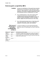
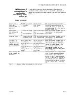
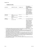
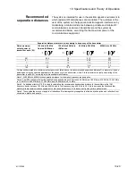


10 Specifications and Theory of Operation
M1132382
10-31
IEC 60601-1 Classification
This system is classified as follows:
•
Class I Equipment.
•
Type B Equipment.
•
Ordinary Equipment.
•
Not for use with flammable anesthetics.
•
Continuous operation.
Standards
Devices used with this anesthesia system shall comply with the
following standards where applicable:
•
Breathing systems and breathing system components
ISO 8835-2.
•
Anesthetic vapor delivery devices ISO 8835-4.
•
Anesthetic agent monitors ISO 11196.
•
Oxygen monitors ISO 7767.
•
Carbon dioxide monitors ISO 9918.
•
Exhaled volume monitors IEC 60601-2-13.
Summary of Contents for Aespire View
Page 1: ...Aespire View User s Reference Manual Software Revision 6 X...
Page 16: ...Aespire View 1 8 M1132382...
Page 46: ...Aespire View 3 16 M1132382...
Page 50: ...Aespire View 4 4 M1132382...
Page 88: ...Aespire View 7 8 M1132382...
Page 112: ...Aespire View 9 10 M1132382...
Page 148: ...Aespire View I 4 M1132382...


