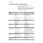
5 Troubleshooting
5-10
05/04 1006-0453-000
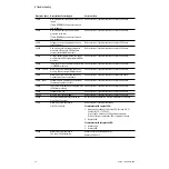
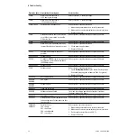
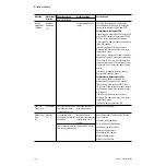
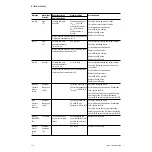
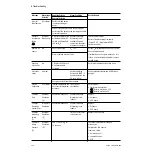
Battery
Failure High
User Alarm
Battery voltage > 16 V
for 10 seconds.
The system continues to
operate, but may fail.
If persists, replace:
• battery
For machines with original CPU:
• PSB
For machines with Integrated CPU:
• CPU board
Battery
Failure Low
User Alarm
The battery voltage is
too low (<7 V) to supply
the system if power
fails.
The battery does not
have enough charge to
power the equipment if
power fails.
If persists, replace:
• battery
For machines with original CPU:
• PSB
For machines with Integrated CPU:
• CPU board
Leave the system plugged in to charge the battery.
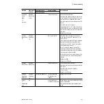
Cal Flow
Sensors
User Alarm
The last flow sensor
calibration failed.
This alarm message indicates that the last flow
sensor’s differential pressure transducer
calibration failed.
With the BTV switch in Bag, ensure sensors are
removed until the “No Insp/No Exp flow
sensor” message appears.
If persists, replace:
• Check for moisture
• Refer to Troubleshooting Flowcharts
(Section 5.5)
Calibrate the flow sensors. Look for water in the
flow sensor tubes. Dry if necessary.
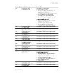
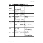
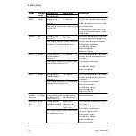
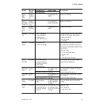
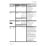
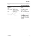
Calibrate O2
Sensor
low
Sensor connected
Offset, slope, or cell
voltage not in range or
O
2
> 110%
Calibrate the O
2
sensor.
If calibration fails, replace the O
2
sensor.
If calibration still fails, replace the SIB board.
Successful calibration of sensor.
Canister
open
User Alarm
The canister release is
open (large leak)
without a bypass
mechanism.
If persists, check:
• canister switch
• harness to SIB
• SIB
• cable from SIB to CPU board
Close the canister release.
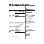
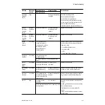
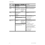
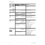
Cannot Drive
Bellows
(
4.X
)
User Alarm
The internal manifold
pressure is higher than
Paw + tolerance.
Check the breathing circuit for leaks or hose
occlusions.
Perform flow sensor calibration.
Check the drive gas check valve.
Check SIB to CPU cabling.
Replace the SIB board.
Replace the CPU board.
Fill the bellows, if empty.
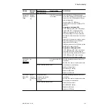
Cardiac
Bypass
User Alarm
The cardiac bypass
option is selected
(Alarm limit menu).
Use the alarm limits menu to change this setting.
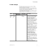
Message
Alarm type/
Priority
Enabling Criteria
Alarm Condition
Service Repair
Removal Criteria
Summary of Contents for Aestiva 7900 SmartVent
Page 1: ...Aestiva 5 7900 Anesthesia Ventilator Technical Reference Manual ...
Page 44: ...Notes 2 28 05 04 1006 0453 000 ...
Page 82: ...Notes 4a 36 05 04 1006 0453 000 ...
Page 116: ...Notes 4b 34 05 04 1006 0453 000 ...
Page 150: ...Notes 5 34 05 04 1006 0453 000 ...
Page 158: ...Notes 6 8 05 04 1006 0453 000 ...
Page 182: ...Notes 7 24 05 04 1006 0453 000 ...
Page 202: ...Notes 8 20 05 04 1006 0453 000 ...
Page 203: ......

