7 Repair Procedures
1006-0453-000 05/04
7-3
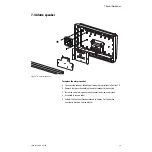
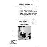
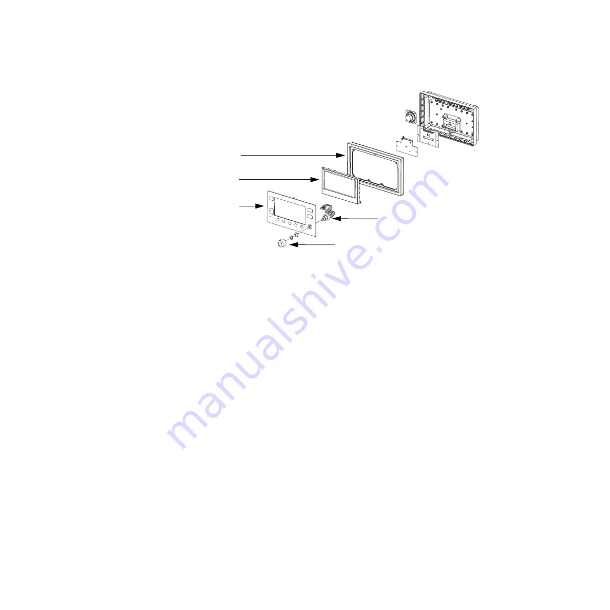
7.2 Keyboard and EL display
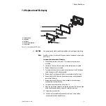
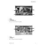
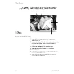
Figure 7-2 • Keyboard and EL Display
w
CAUTION
Use an approved static control workstation and wrist grounding strap.
Note
For MRI machines, refer to the MRI service manual supplement regarding the
EMC shield.
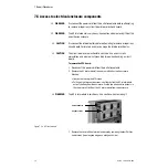
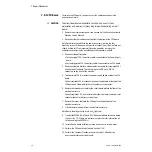
To remove the keyboard and EL display:
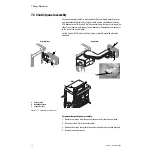
1. Follow the instructions in Section 7.1 to remove the control panel
assembly.
2. Loosen the screws on the rear corners of the control panel assembly.
3. Remove the back cover assembly.
4. To separate the front and rear assemblies, disconnect the 50-pin ribbon
cable from connector J2 of the keyboard.
5. Remove the 20-pin ribbon cable from its connector on the EL display.
6. Remove the four M3 Keps nuts from mounting studs on keyboard and
remove the EL display.
7. Remove the seven M4 Keps nuts from keyboard studs and remove
keyboard from the front housing.
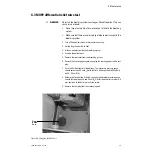
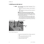
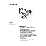
8. To replace the encoder switch, see Section 7.3.
9. When you replace the keyboard, remove the protective film from the back
of the new keyboard window, clean, and check for scratches.
10. Assemble in reverse order.
11. Perform the Checkout Procedure found in Section 3 of the Aestiva
Anesthesia Machine Service Manual.
4
5
AB.29.072
1
2
3
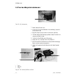
1. Front housing
2. EL display
3. Keyboard
4. Rotary encoder switch
5. Control knob
Summary of Contents for Aestiva 7900 SmartVent
Page 1: ...Aestiva 5 7900 Anesthesia Ventilator Technical Reference Manual ...
Page 44: ...Notes 2 28 05 04 1006 0453 000 ...
Page 82: ...Notes 4a 36 05 04 1006 0453 000 ...
Page 116: ...Notes 4b 34 05 04 1006 0453 000 ...
Page 150: ...Notes 5 34 05 04 1006 0453 000 ...
Page 158: ...Notes 6 8 05 04 1006 0453 000 ...
Page 182: ...Notes 7 24 05 04 1006 0453 000 ...
Page 202: ...Notes 8 20 05 04 1006 0453 000 ...
Page 203: ......

