7 Repair Procedures
7-6
05/04 1006-0453-000
7.5 Access to electrical enclosure components
w
WARNING
Disconnect the power cord from the outlet receptacle before attempting
to remove or repair any circuit board to avoid shock hazard.
w
WARNING
The AC inlet module is very heavy. Use caution when removing it from the
anesthesia enclosure.
w
CAUTION
Disconnect the internal battery before attempting to remove or repair any
circuit board. Failure to do so may damage the internal electronics.
w
CAUTION
The circuit boards are electrostatic sensitive. Use an anti-static
workstation and wear a wrist grounding strap when handling a circuit
board.
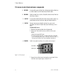
To remove the CPU board:
1.
Disconnect the power cord from the outlet receptacle.
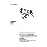
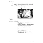
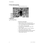
2. Remove the AC inlet module from the rear of the Aestiva Anesthesia
Machine.
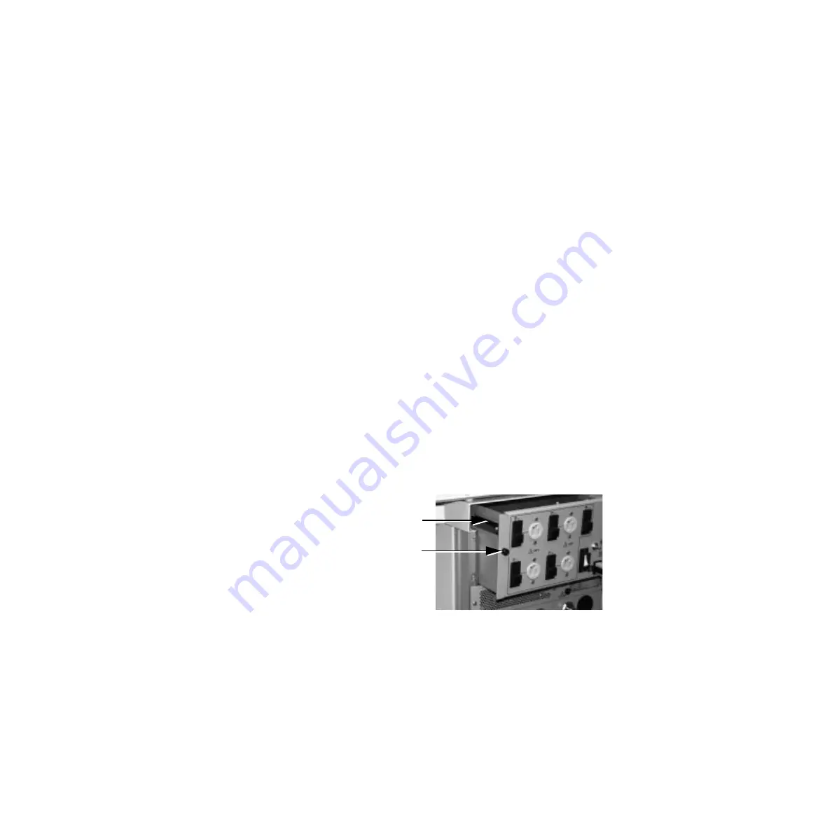
• Loosen the two captive M4 screws.
• Pulling on the two captive screws, cautiously slide the AC inlet module
out only halfway from the enclosure. Use the two side handles (cutouts in
the sheet metal) to lift out the AC inlet module from the enclosure.
w
WARNING
The AC inlet module is very heavy. Use caution when removing it.
.
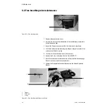
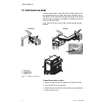
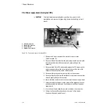
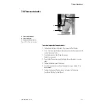
Figure 7-5 • AC Inlet module
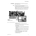
3. Remove the cover of the electrical enclosure by removing the four Phillips
head screws (two along top edge, one along each side).
Captive screws
Cutout handles
Summary of Contents for Aestiva 7900 SmartVent
Page 1: ...Aestiva 5 7900 Anesthesia Ventilator Technical Reference Manual ...
Page 44: ...Notes 2 28 05 04 1006 0453 000 ...
Page 82: ...Notes 4a 36 05 04 1006 0453 000 ...
Page 116: ...Notes 4b 34 05 04 1006 0453 000 ...
Page 150: ...Notes 5 34 05 04 1006 0453 000 ...
Page 158: ...Notes 6 8 05 04 1006 0453 000 ...
Page 182: ...Notes 7 24 05 04 1006 0453 000 ...
Page 202: ...Notes 8 20 05 04 1006 0453 000 ...
Page 203: ......


