7 Repair Procedures
1006-0453-000 05/04
7-9
7.5.2 Firmware replacement procedure
w
CAUTION
The circuit board and EEPROMs are electrostatic sensitive. Use an
approved static control workstation and wrist grounding strap.
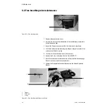
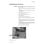
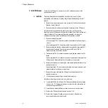
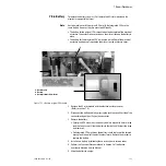
13.Place the CPU board on an approved static control workstation.
14.Note the label and orientation of each EEPROM to ensure they are properly
transferred to the replacement board.
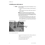
15.Use a PLCC chip extraction tool to remove the two EEPROMs, U14 and U23.
Insert the two prongs on the extractor tool into the slotted corners of the
EEPROM socket.
16.Install the new EEPROMs, noting the label to ensure the correct chip is
placed in the correct socket. Align the EEPROM notch with the socket notch
and press the chip down firmly.
CPU board tests
Whenever you replace the CPU board and/or the EEPROMs (U14 and U23), or
perform the software upgrade, perform the following tests:
• Select the altitude (Section 4)*
• Select the drive gas (Section 4)*
• Cal O
2
Sensor (Section 4)
• Cal Flow Sensor (Section 4)
• Cal Pressure Sensitivity (Section 4)
• Cal Flow Valve (Section 4)
• Cal Bleed Resistor (Section 4)
• Perform the Checkout Procedure found in Section 3 of the Aestiva
Anesthesia Machine Service Manual.
* Even if these settings appear to be set correctly, they must be deliberately
changed and set back to their proper setting.
Summary of Contents for Aestiva 7900 SmartVent
Page 1: ...Aestiva 5 7900 Anesthesia Ventilator Technical Reference Manual ...
Page 44: ...Notes 2 28 05 04 1006 0453 000 ...
Page 82: ...Notes 4a 36 05 04 1006 0453 000 ...
Page 116: ...Notes 4b 34 05 04 1006 0453 000 ...
Page 150: ...Notes 5 34 05 04 1006 0453 000 ...
Page 158: ...Notes 6 8 05 04 1006 0453 000 ...
Page 182: ...Notes 7 24 05 04 1006 0453 000 ...
Page 202: ...Notes 8 20 05 04 1006 0453 000 ...
Page 203: ......


