7 Repair Procedures
1006-0453-000 05/04
7-11
7.5.4 Power supply (for Integrated CPU)
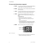
w
CAUTION
The circuit boards are electrostatic sensitive. Use an anti-static
workstation and wear a wrist grounding strap when handling a circuit
board.
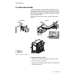
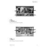
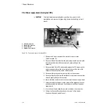
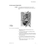
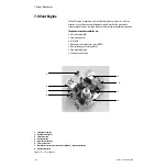
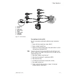
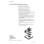
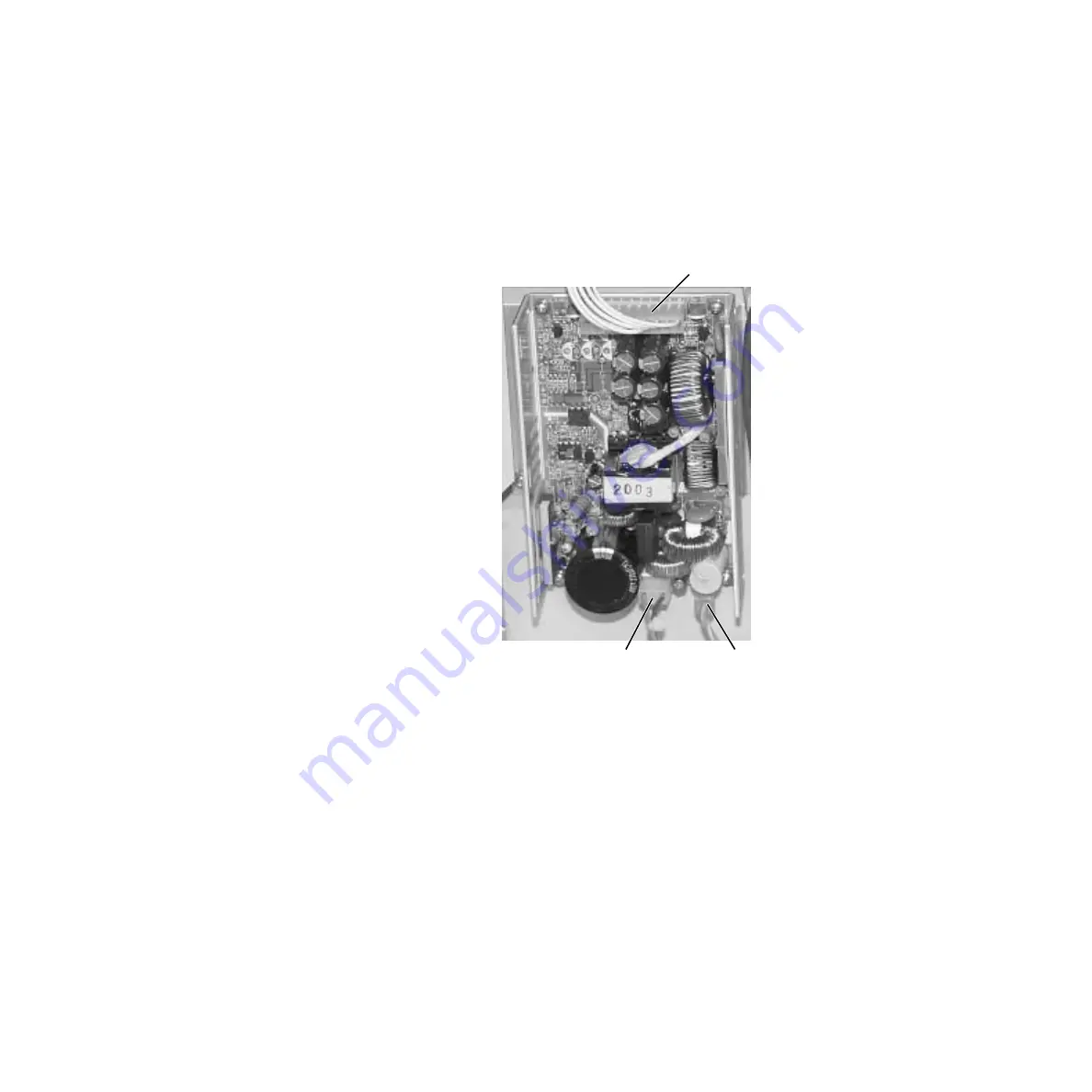
Figure 7-9 • Power supply (for Integrated CPU)
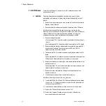
1. Remove the AC inlet module and the electrical enclosure cover
2. Disconnect the line power inlet connector and the ground wire at the
bottom edge of the power supply.
3. Disconnect the power outlet connector at the top edge of the power supply.
4. Remove the two nuts that hold the power supply assembly to the back plate
of the electrical enclosure.
5. Transfer the power supply mounting bracket to the new power supply.
6. To install a new power supply, follow the removal instructions in reverse
order.
7. Perform the Checkout Procedure found in Section 3 of the Aestiva
Anesthesia Machine Service Manual.
1
1. Line power
2. Chassis ground
3. Power output
2
3
Summary of Contents for Aestiva 7900 SmartVent
Page 1: ...Aestiva 5 7900 Anesthesia Ventilator Technical Reference Manual ...
Page 44: ...Notes 2 28 05 04 1006 0453 000 ...
Page 82: ...Notes 4a 36 05 04 1006 0453 000 ...
Page 116: ...Notes 4b 34 05 04 1006 0453 000 ...
Page 150: ...Notes 5 34 05 04 1006 0453 000 ...
Page 158: ...Notes 6 8 05 04 1006 0453 000 ...
Page 182: ...Notes 7 24 05 04 1006 0453 000 ...
Page 202: ...Notes 8 20 05 04 1006 0453 000 ...
Page 203: ......

