7 Repair Procedures
1006-0453-000 05/04
7-15
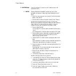
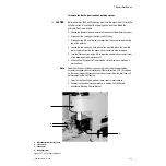
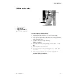
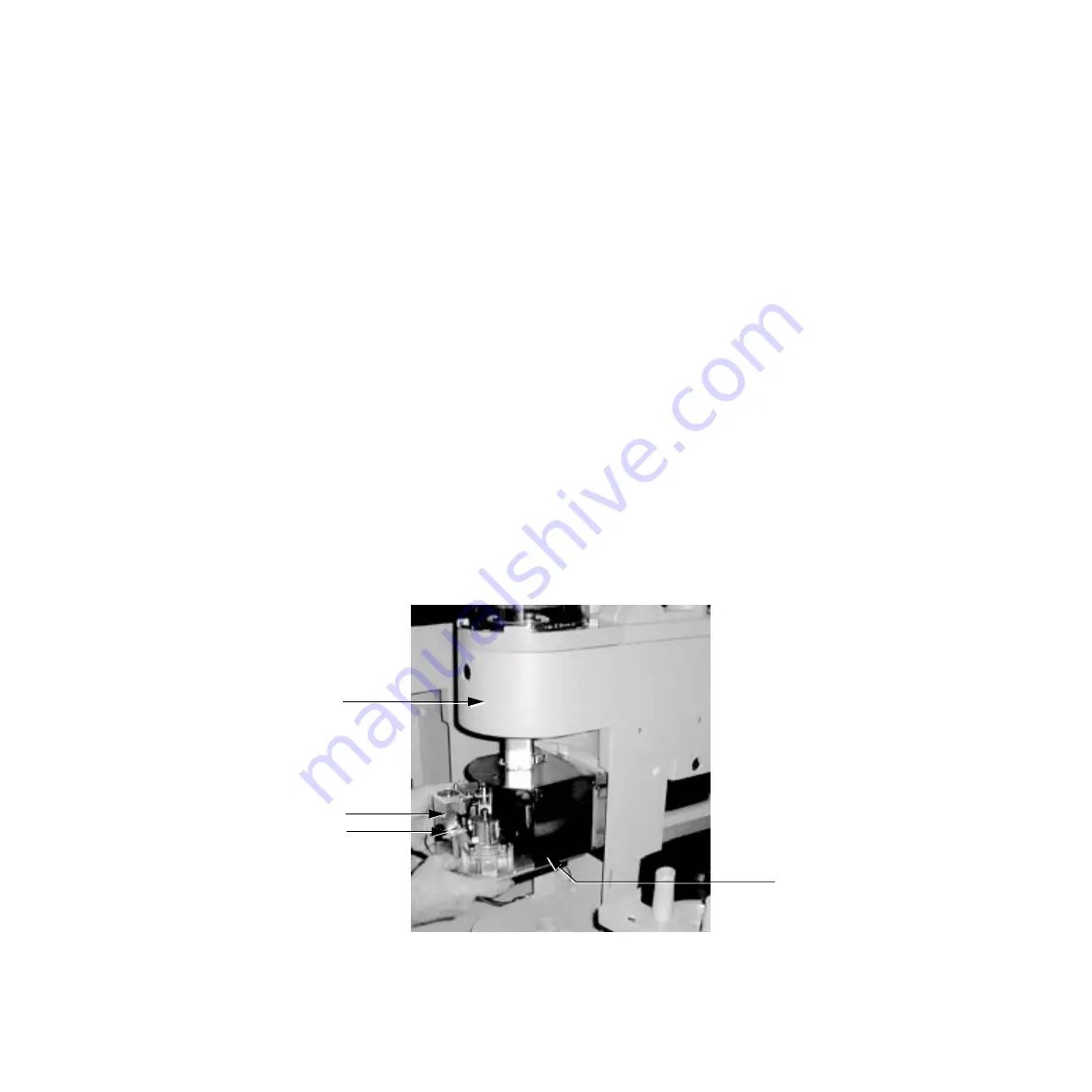
To remove the Vent Engine from the breathing system:
w
CAUTION
Before servicing the Vent Engine you must turn the machine off, close the
cylinder valves, disconnect the supply gases, and then bleed the
pressure from the machine.
1. Loosen the thumbscrew and remove the rear cover of the breathing system.
2. Disconnect the supply gas line from the GIV fitting.
3. Disconnect the GIV and flow valve cables from the connector board at the
top of the housing.
4. Loosen the two screws on both sides of the manifold plate. The manifold
plate is grooved to allow the pneumatic assembly to slide into place.
5. Turn the lifter hex screw on the GIV to lower the double tube assembly clear
of the exhalation valve interface cuff.
6. Slide the Vent Engine out of the breathing system frame and place on a
work surface.
Note
Newer Vent Engines include a spring on the inside tube to keep the tube
assembly engaged with the interface cuff (Refer to section 8.7.6). Push down
on the tube crossbar to disengage the tube assembly from the interface cuff
before removing the Vent Engine.
7. To install the Vent Engine, perform these steps in reverse order.
8. Perform the Checkout Procedure found in Section 3 of the Aestiva
Anesthesia Machine Service Manual.
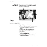
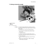
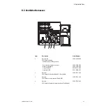
1. Breathing system housing (rear)
2. Lever Screw
3. Vent Engine
4. Mounting screws
Figure 7-13 • Vent Engine removal
4
3
1
2
Summary of Contents for Aestiva 7900 SmartVent
Page 1: ...Aestiva 5 7900 Anesthesia Ventilator Technical Reference Manual ...
Page 44: ...Notes 2 28 05 04 1006 0453 000 ...
Page 82: ...Notes 4a 36 05 04 1006 0453 000 ...
Page 116: ...Notes 4b 34 05 04 1006 0453 000 ...
Page 150: ...Notes 5 34 05 04 1006 0453 000 ...
Page 158: ...Notes 6 8 05 04 1006 0453 000 ...
Page 182: ...Notes 7 24 05 04 1006 0453 000 ...
Page 202: ...Notes 8 20 05 04 1006 0453 000 ...
Page 203: ......

