7 Repair Procedures
1006-0453-000 05/04
7-23
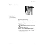
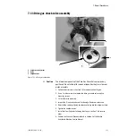
7.11 Drive gas check valve assembly
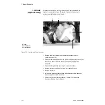
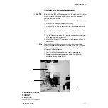
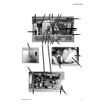
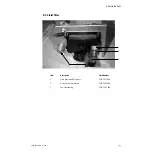
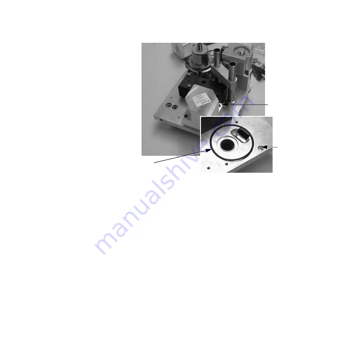
1. Captive mounting screws
2. O-ring
3. Alignment hole
Figure 7-21 • Drive gas check valve
w
Caution
The internal components of the Drive Gas Check Valve are precisely
positioned. Do not attempt to remove or reposition the glass sleeve or
piston assembly
1. Follow the instructions in Section 7.6 to remove the Vent Engine.
2. Use a 3 mm hex wrench to loosen the drive gas check valve captive
mounting screws.
3. Lift out the valve assembly.
4. Inspect the O-ring and valve seat for damage. Replace as necessary.
5. Reinstall the valve by aligning the check valve pin into the alignment hole.
6. Tighten the captive screws.
7. Install the Vent Engine by following the steps in Section 7.6 in reverse
order.
8. Perform the Checkout Procedure found in Section 3 of the Aestiva
Anesthesia Machine Service Manual.
1
2
3
Summary of Contents for Aestiva 7900 SmartVent
Page 1: ...Aestiva 5 7900 Anesthesia Ventilator Technical Reference Manual ...
Page 44: ...Notes 2 28 05 04 1006 0453 000 ...
Page 82: ...Notes 4a 36 05 04 1006 0453 000 ...
Page 116: ...Notes 4b 34 05 04 1006 0453 000 ...
Page 150: ...Notes 5 34 05 04 1006 0453 000 ...
Page 158: ...Notes 6 8 05 04 1006 0453 000 ...
Page 182: ...Notes 7 24 05 04 1006 0453 000 ...
Page 202: ...Notes 8 20 05 04 1006 0453 000 ...
Page 203: ......

