2 Theory of Operation
2-4
05/04 1006-0453-000
2.3.1 Ventilator control
electronics
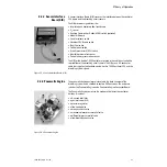
The ventilator control electronics is found in the electrical enclosure of the
Aestiva machine behind the AC Inlet module.
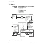
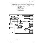
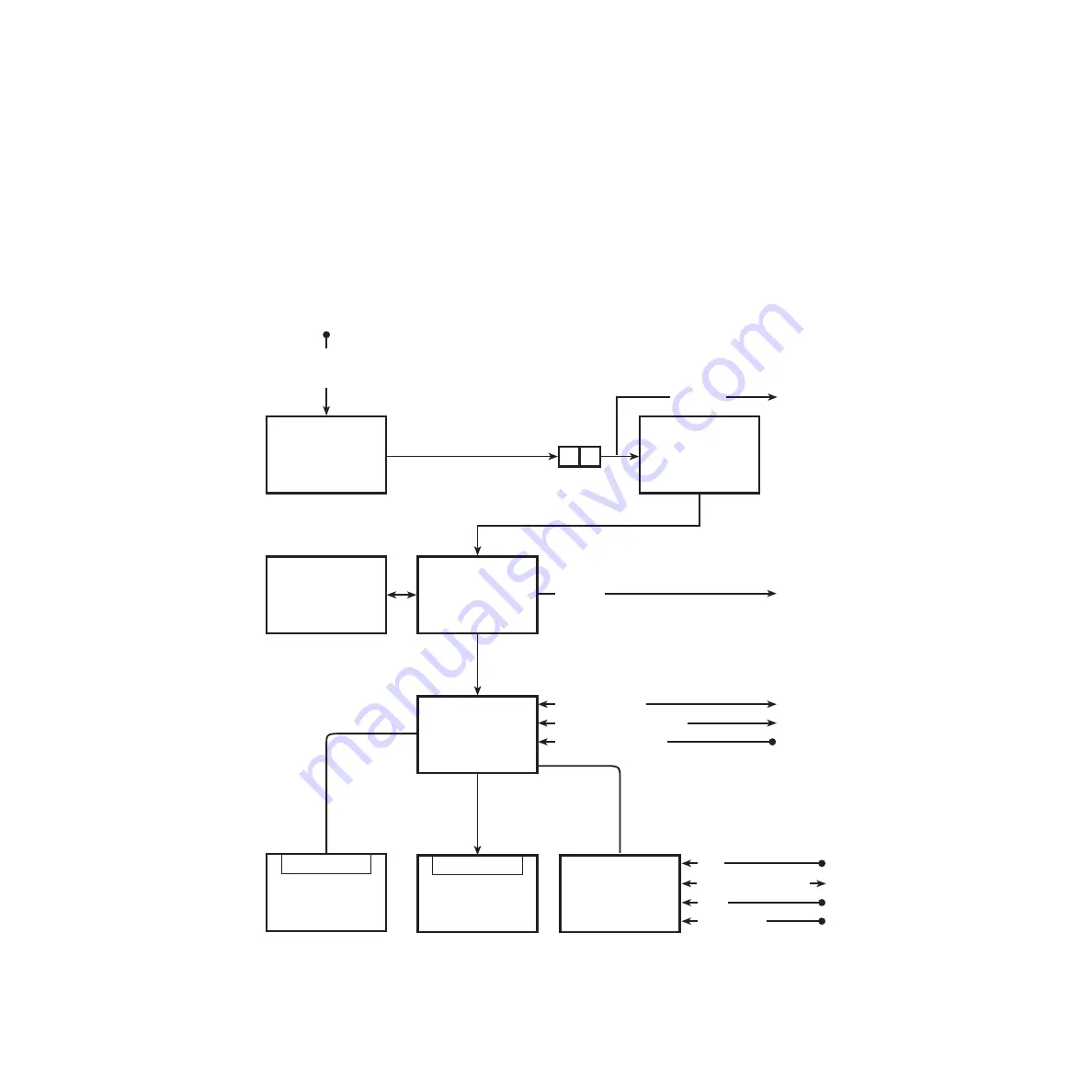
In the original Aestiva machines, the power supply and the CPU are on
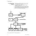
separate boards, as shown in Figure 2-2.
The ventilator control electronics includes the power supply and the CPU. The
power supply receives AC power from the machine’s AC Inlet module. All the
power necessary to operate the ventilator and light package comes from the
power supply. The CPU controls operation of the ventilator.
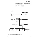
Figure 2-2 • Aestiva 7900 Ventilator functional block diagram (Original CPU)
-Fuses
-Voltage Selector
-Filter
Connector Board
Connector Board
100-120 VAC
220-240 VAC
50/60 Hz
AC Inlet Module
Toroid
Battery
Power Supply
Board
CPU Board
Front Panel
Assembly
Pneumatic
Engine
Sensor
Interface Board
Proprietary RS232C
Primary RS232C On/StandBy
Vent On/StandBy Switch
O2 Supply Switch and O2 Flush Switch
Patient Interface Harness
ACGO
Tec6 Outlet
Task Light
BCID
Oxygen Sensor
AB.29.087
Summary of Contents for Aestiva 7900 SmartVent
Page 1: ...Aestiva 5 7900 Anesthesia Ventilator Technical Reference Manual ...
Page 44: ...Notes 2 28 05 04 1006 0453 000 ...
Page 82: ...Notes 4a 36 05 04 1006 0453 000 ...
Page 116: ...Notes 4b 34 05 04 1006 0453 000 ...
Page 150: ...Notes 5 34 05 04 1006 0453 000 ...
Page 158: ...Notes 6 8 05 04 1006 0453 000 ...
Page 182: ...Notes 7 24 05 04 1006 0453 000 ...
Page 202: ...Notes 8 20 05 04 1006 0453 000 ...
Page 203: ......

