2 Theory of Operation
2-6
05/04 1006-0453-000
2.3.2 Control panel and
display
The control panel on the Aestiva 7900 Ventilator is either outboard (on an
arm) or on a hinge to fold flat against the machine (depending on the option
ordered) and is made to permit you to grip the panel and push the buttons
with your thumbs. The ventilator control panel position is easily adjusted.
For the Aestiva/5 MRI machine, the display is centrally mounted above the
flowhead.
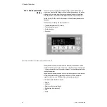
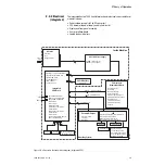
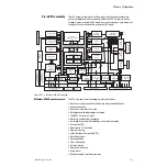
The front panel assembly has four submodules:
• The electroluminescent (EL) display
• The keyboard front panel
• A rotary encoder
• A speaker
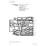
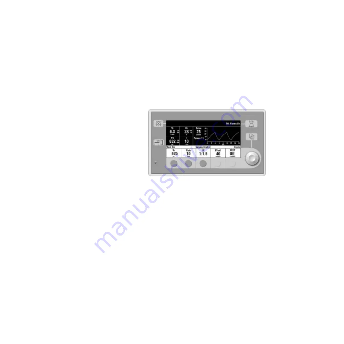
Figure 2-4 • Ventilator control panel with software version 4.X
The keyboard and rotary encoder are used to control the operations of the
ventilator. The front panel uses a three step — selection, change, and approve
— setting scheme to prevent unwanted selections. The speaker supplies audio
input to the operator.
Logical layout of primary controls is left to right in the sequence: tidal volume
or inspiratory pressure level, respiratory frequency, I:E ratio, maximum
inspiratory pressure, and PEEP (positive end expiratory pressure).
Primary Ventilator interfaces include:
• Display
• Soft keys
• Rotary encoder (control wheel)
• Knob button (control wheel)
• LED
• Audio
Summary of Contents for Aestiva 7900 SmartVent
Page 1: ...Aestiva 5 7900 Anesthesia Ventilator Technical Reference Manual ...
Page 44: ...Notes 2 28 05 04 1006 0453 000 ...
Page 82: ...Notes 4a 36 05 04 1006 0453 000 ...
Page 116: ...Notes 4b 34 05 04 1006 0453 000 ...
Page 150: ...Notes 5 34 05 04 1006 0453 000 ...
Page 158: ...Notes 6 8 05 04 1006 0453 000 ...
Page 182: ...Notes 7 24 05 04 1006 0453 000 ...
Page 202: ...Notes 8 20 05 04 1006 0453 000 ...
Page 203: ......

