

2 Theory of Operation
2-10
05/04 1006-0453-000
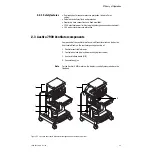
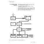
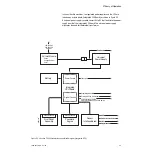
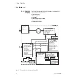
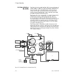
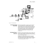
2.4.3 Power supply
(original)
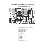
The power supply performs seven functions:
• AC to DC converter
• DC to DC step-down converter
• Battery charger
• Multiple output DC regulator
• Battery charge/discharge current monitor
• Battery voltage monitor
• Task light power supply 12V
Figure 2-9 • Ventilator power supply (Original CPU)
Transformer
Battery Voltage &
Current Sense
OVP &
Current Limit
Rectifier
& Filter
Rectifier
& Filter
Secondary DC to DC
Converter #2
VSW
Linear
Regulator
VBOOT
Linear
Regulator
Linear
Regulator
Linear
Regulator
Linear
Regulator
Step-Down
Controller
12 V Battery
Battery Charge
Controller
Primary
DC to DC
Converter
Bridge Rectifier
& Filter Caps
Toroid
Isolation
Transformer
Entry Module
- EMI Filter
- Fuse
- Voltage Selector
+5V VDD Digital
IBatt,VBatt
Charger
Disconnect
0.25A
+5.8V
+5.5V Valves Supply
30-60 VDC
VB
VBUS
+16.6V
+15V Analog
Secondary
DC to DC
Converter #1
-15V Analog
ON/Standby
Switch
+12V (Task Lights)
24-45
VAC
VSW
(+5V VDD Fail Buzzer
+10-14.5V
VH_EL
Power
Cord
Thermal
Breaker
Linear
Regulator
AC_LED
Rem_On
AB.29.097
Summary of Contents for Aestiva 7900 SmartVent
Page 1: ...Aestiva 5 7900 Anesthesia Ventilator Technical Reference Manual ...
Page 44: ...Notes 2 28 05 04 1006 0453 000 ...
Page 82: ...Notes 4a 36 05 04 1006 0453 000 ...
Page 116: ...Notes 4b 34 05 04 1006 0453 000 ...
Page 150: ...Notes 5 34 05 04 1006 0453 000 ...
Page 158: ...Notes 6 8 05 04 1006 0453 000 ...
Page 182: ...Notes 7 24 05 04 1006 0453 000 ...
Page 202: ...Notes 8 20 05 04 1006 0453 000 ...
Page 203: ......


