2 Theory of Operation
1006-0453-000 05/04
2-13
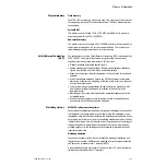
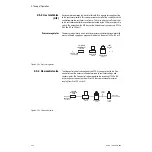
2.4.6 CPU assembly
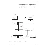
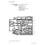
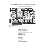
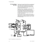
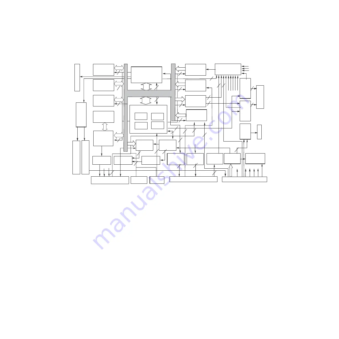
The CPU assembly contains all of the major circuit functions necessary to
control ventilator operation. In the original Aestiva 7900 machines, these
functions are on a separate CPU board. For current machines, they are part of
the digital circuits section of the integrated CPU board.
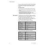
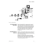
Figure 2-11 • Ventilator CPU block diagram
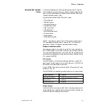
Motorola 68340 processor core
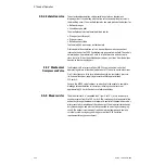
The CPU core consists of the following internal functions:
• Bus access control signals for all memory and peripheral devices
• Interrupt handling
• Clocks and timers for the system
• Background software development mode
• Two RS232C serial I/O ports
• Baud rate generator for serial ports
• Hard (power-up) and soft (watchdog error) reset generation
• Data bus buffers
• Memory and I/O decoding
• Program memory
• Safety Relevant Computing (SRC)
• Watchdog system
• Data acquisition
• Flow valve control
• Inlet valve drive
• Front panel interface
• Audio alarm
• Regulator output/manifold pressures
1
2
2
9
11
4
2
12
1
10
5
1
1
1
D0-D15
4
D0-D15
14
2
2
5
1
7
2
14
1
6
6
1
4
1
3
3
3
MC68340
MICROCONTROLLER
EEPROM
( 2K X 8 )
STATIC RAM
( 128K X 16 )
FLASH MEM
( 512K X 16 )
VENTILATION
CONTROL
ADDRESS
DECODING
ADC
SEQUENCER
WATCHDOG
LOGIC
12-BIT A/D
CONVERTER
D0-D15
DIGITAL
INPUT 0
24-CHANNEL
MUTIPLEXER
D8-D15
A0-A11,
D8-D15
12-BIT D/A
CONVERTER
SYSTEM DATA BUS & ADDRESS BUS
Front Panel Assembly
Connector
LM4860M
AUDIO AMP
EPLD-EPM7064
ANALOG
SIGNALS
SIB_+12V
10VA LIMIT
A0-A20
D0-D15
A20, A0, A1
A14-A17,
D8-D10
+5.8V
SIB_12V
1.225V
FLOW V
A
L
V
E
DRIVE
INLET
V
A
L
V
E
DRIVE
A0-A18,
D0-D15
D0-D15
DIGITAL
INPUT 1
SED1351F
VIDEO
CONTROLLER
VIDEO SRAM
( 32K X 8 )
V
A0-V
A1
1
VD8-VD15
+5V
+5.8V +15V
-15V
YM2413
AUDIO
CHIP
FERRITE
BEADS
DS1232
WATCHDOG
& RESET
A0-A18,
D0-D15
A0-A10,
D8-D15
Pneumatic Engine
Connector
SERIAL
EEPROM
INTERFACE
+15V
RS232C
DRIVER
Production Connector
Proprietary RS232C
Connector
+5V
VH_EL
SIB Connector
VH_EL
FREQUENCY
DIVIDER
VH_EL
Primary RS232C
VOLTAGE TEST
POINTS
Power Supply Connector
V
DD
MONITOR
O
2
Flush
Connector
O
2
Supply
Connector
+5V LOSS
ALARM
Buzzer
VSW
+15V
-15V
P12V_LIGHT
Connector
Summary of Contents for Aestiva 7900 SmartVent
Page 1: ...Aestiva 5 7900 Anesthesia Ventilator Technical Reference Manual ...
Page 44: ...Notes 2 28 05 04 1006 0453 000 ...
Page 82: ...Notes 4a 36 05 04 1006 0453 000 ...
Page 116: ...Notes 4b 34 05 04 1006 0453 000 ...
Page 150: ...Notes 5 34 05 04 1006 0453 000 ...
Page 158: ...Notes 6 8 05 04 1006 0453 000 ...
Page 182: ...Notes 7 24 05 04 1006 0453 000 ...
Page 202: ...Notes 8 20 05 04 1006 0453 000 ...
Page 203: ......

