6/ Repair Procedures
1503-0151-000
5/26/0
6-45
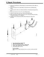
5. Remove the Tabletop from the Modulus SE. See Modulus SE Service Manual
section 5.3.
6. Disconnect the four color coded tubing connectors from the SIB Assembly
tubing.
7. Carefully cut and remove the cable ties that secure the electrical harness to the
pan.
8. Disconnect connector J1 from P1 on the SIB Assembly.
9. Open the Vanity panel on the rear of the Anesthesia Machine.
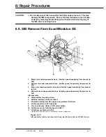
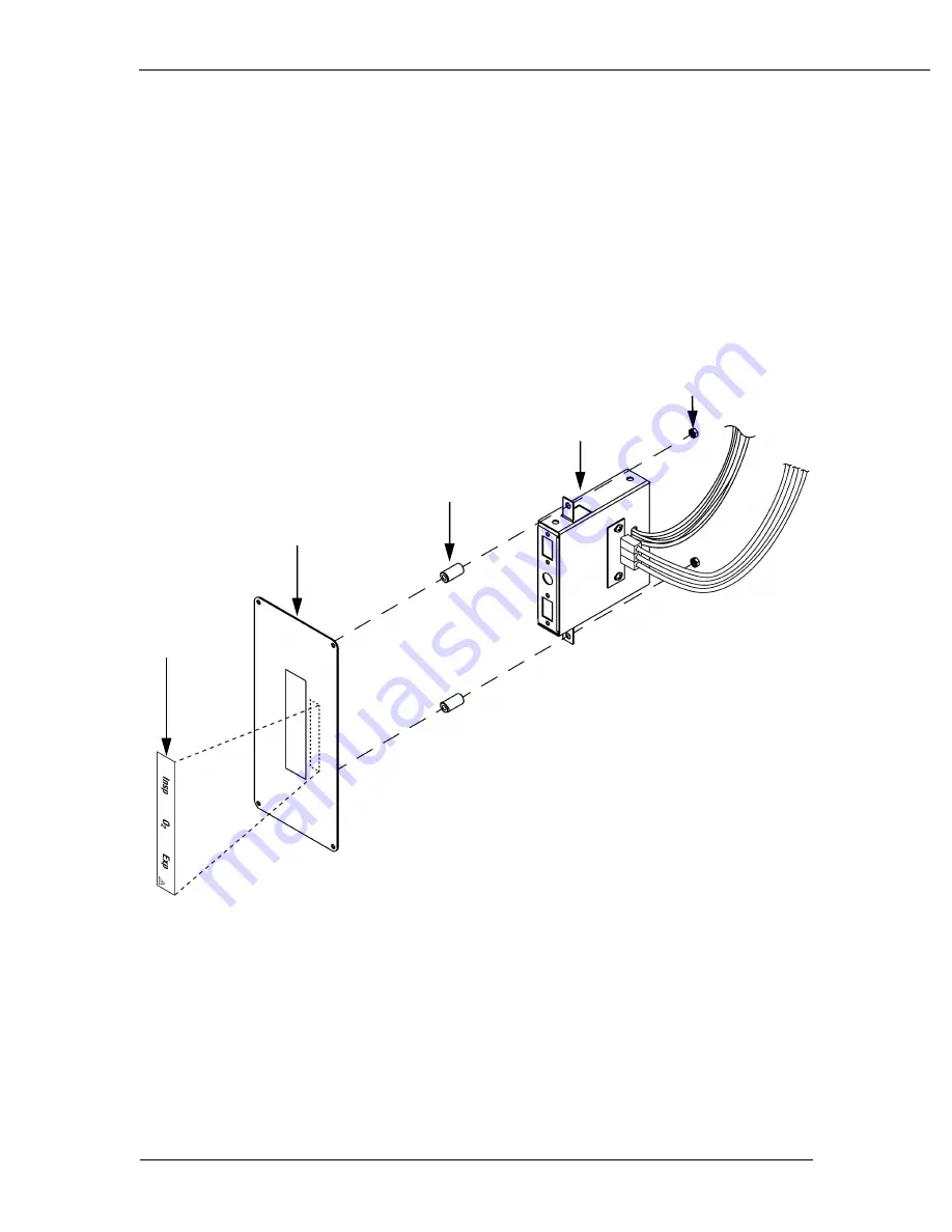
10. While supporting the Interface Assembly, remove the two M4 keps nuts (item
5, Figure 6-37) using a 7 mm nutdriver.
11. Carefully route the harness and tubing through the pan to remove the
assembly.
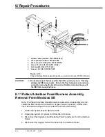
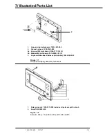
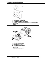
1.
Label, patient interface, 1001-3464-000
2.
Harness SA, SIB, 1503-3081-000
3.
Panel, sensor interface, Modulus SE, 1004-3933-000
4.
Spacer, sensor interface panel, 1004-3934-000 (2)
5.
Nut, keps M4, 0144-3717-314 (2)
Figure AA.85.083
Patient Interface/Harness Assembly (shown mounted on the Modulus SE left
side)
AA.85083
1
2
3
4
5
Summary of Contents for Aestiva 7900 SmartVent
Page 2: ...1503 0151 000 3 27 97 ...
Page 4: ...1503 0151 000 3 27 97 ...
Page 12: ...Notes viii 1503 0151 000 3 27 97 ...
Page 18: ...1 Introduction 1 6 1503 0151 000 5 26 0 Notes ...
Page 44: ...2 Theory of Operation 2 26 1503 0151 000 3 27 97 Notes ...
Page 46: ...3 Post Service Checkout 3 2 1503 0151 000 5 26 0 Notes ...

