

4/Tests and Troubleshooting
4-16
1503-0151-000
5/26/0
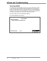
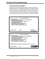
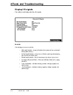
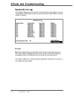
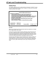
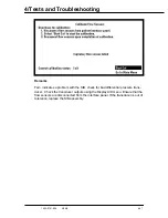
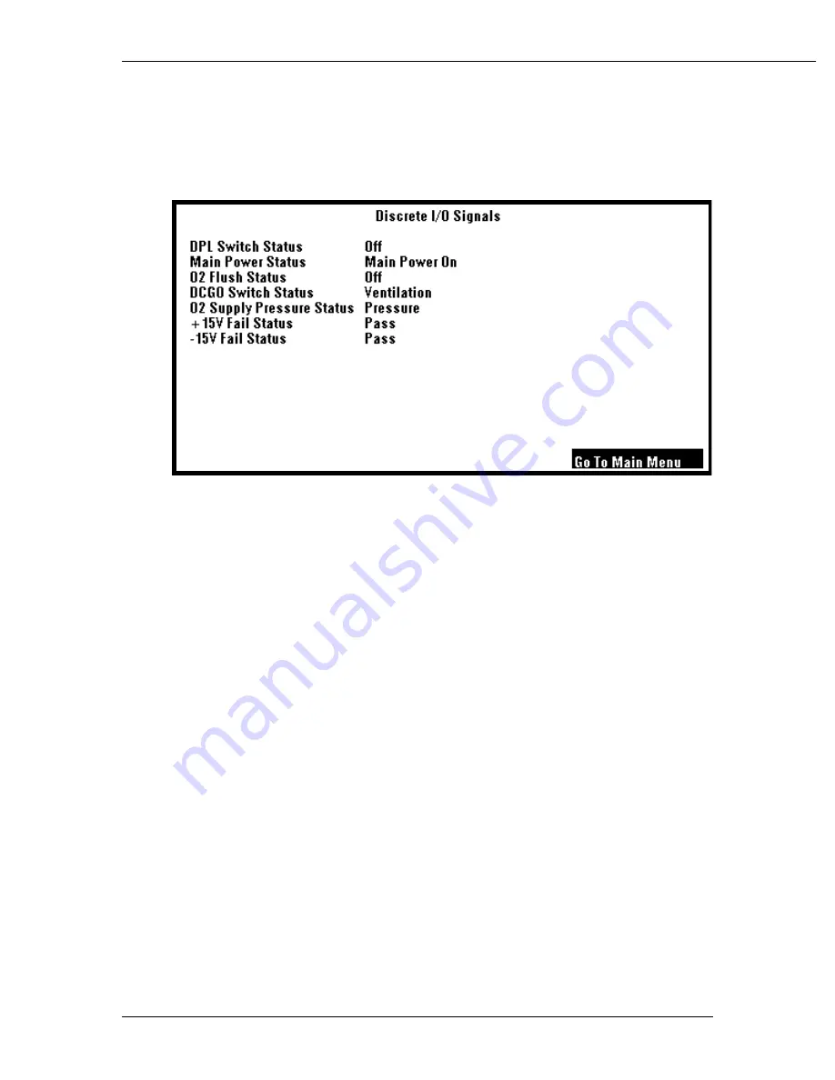
Display I/O signals
The software will display all of the I/O signals.
Remarks
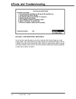
This display is a service tool for:
•
DPL switch status - shows off unless drive pressure has exceeded
limit (switch is N.O.)
•
O
2
flush switch status - shows on or off when pushing and releasing
gas machine O
2
flush valve
•
DCGO switch status - French machines only either Vent or Aux
•
O
2
Supply Pressure Status - Pressure indicates there is O
2
supply
pressure
•
+15V Fail Status - indicates analog positive voltage supplies are
within range
•
-15V Fail Status - indicates analog negative voltage supplies are
within range
Summary of Contents for Aestiva 7900 SmartVent
Page 2: ...1503 0151 000 3 27 97 ...
Page 4: ...1503 0151 000 3 27 97 ...
Page 12: ...Notes viii 1503 0151 000 3 27 97 ...
Page 18: ...1 Introduction 1 6 1503 0151 000 5 26 0 Notes ...
Page 44: ...2 Theory of Operation 2 26 1503 0151 000 3 27 97 Notes ...
Page 46: ...3 Post Service Checkout 3 2 1503 0151 000 5 26 0 Notes ...


