7 Repair Procedures
7-2
05/04 1006-0453-000
7.1 Control panel assembly
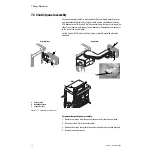
The control panel assembly is mounted on either a Folding Display Mount or
on a repositionable Display Arm. Signals between the control panel and the
CPU board are sent through a 50-pin connector cable that passes through the
side of the machine (and through the outboard arm if equipped) and connects
to the rear of the control panel.
For the Aestiva/5 MRI machine, the display is centrally mounted above the
flowhead.
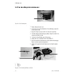
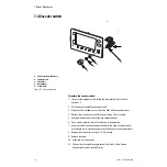
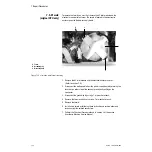
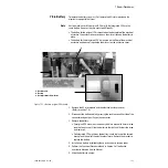
Figure 7-1 • Ventilator control panel
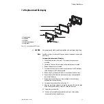
To remove the control panel assembly:
1. Remove the screws from the connector cover and slide the cover back.
2. Disconnect the 50-pin connector cable.
3. Remove the screws that attach the control panel to the mounting brackets.
4. Remove the control panel.
1
2
3
AA.96.076
2
2
AA.96.075
1
3
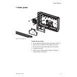
Display Mount
Display Arm
1
2
AA.96.253
MRI
1. Control panel
2. Mounting brackets
3. Connector cover
Summary of Contents for Aestiva 7900 SmartVent
Page 1: ...Aestiva 5 7900 Anesthesia Ventilator Technical Reference Manual ...
Page 44: ...Notes 2 28 05 04 1006 0453 000 ...
Page 82: ...Notes 4a 36 05 04 1006 0453 000 ...
Page 116: ...Notes 4b 34 05 04 1006 0453 000 ...
Page 150: ...Notes 5 34 05 04 1006 0453 000 ...
Page 158: ...Notes 6 8 05 04 1006 0453 000 ...
Page 182: ...Notes 7 24 05 04 1006 0453 000 ...
Page 202: ...Notes 8 20 05 04 1006 0453 000 ...
Page 203: ......

