7 Repair Procedures
7-8
05/04 1006-0453-000
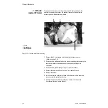
7.5.1 CPU Board
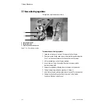
To remove the CPU board, you must access the cable connections in the
pneumatic enclosure.
w
CAUTION
The circuit boards are electrostatic sensitive. Use an anti-static
workstation and wear a wrist grounding strap when handling a circuit
board.
1. Remove the machines rear panel (see Section 4 of the Aestiva Anesthesia
Machine Service Manual).
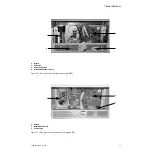
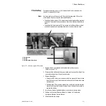
2. Disconnect the four cable connectors from the bottom of the CPU board.
Note: For better accessibility to the cable connectors, remove the four
mounting screws for the pneumatic manifold standoffs, pull the manifold out
slightly and lower it. Front accessibility can be gained by removing the
vaporizers and removing the panel beneath the vaporizer manifold.
3. Disconnect the battery cable.
• For the original CPU, the battery cable is connected to the Power Supply
board.
• For the Integrated CPU, the battery cable is connected to the CPU board.
4. Disconnect the two interface ribbon cables (one cable for Integrated CPU)
near the top of the board. The cable(s) go to the DB-9 and DB-15
connectors on the back of the machine.
5. For the original CPU, disconnect the power supply ribbon cable at the CPU
board.
For the Integrated CPU, disconnect the power supply cable at the top of the
CPU board and (if applicable) the task light harness connector.
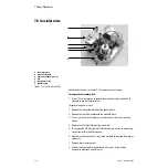
6. Remove the three hex nuts holding the circuit board plate to the floor of the
electrical enclosure.
For the Integrated CPU, also remove the bracket that holds the power inlet
connector (hex nut at bottom, screw at top).
7. Remove the screws that hold the CPU board to the back plate of the
electrical enclosure.
8. Lift and remove the board from the electrical enclosure.
Note: Reuse the old gasket to insure an O
2
tight seal.
9. Transfer the EEPROMs (U14 and U23) from the old board to the new board.
(See
Section 7.5.2 Firmware replacement procedure
for information on
safely handling the EEPROMs.)
10. Install the new board by following these instructions in reverse order.
11. Perform the CPU board tests found in Section 7.5.2.
12. Perform the Checkout Procedure found in Section 3 of the Aestiva
Anesthesia Machine Service Manual.
Summary of Contents for Aestiva 7900 SmartVent
Page 1: ...Aestiva 5 7900 Anesthesia Ventilator Technical Reference Manual ...
Page 44: ...Notes 2 28 05 04 1006 0453 000 ...
Page 82: ...Notes 4a 36 05 04 1006 0453 000 ...
Page 116: ...Notes 4b 34 05 04 1006 0453 000 ...
Page 150: ...Notes 5 34 05 04 1006 0453 000 ...
Page 158: ...Notes 6 8 05 04 1006 0453 000 ...
Page 182: ...Notes 7 24 05 04 1006 0453 000 ...
Page 202: ...Notes 8 20 05 04 1006 0453 000 ...
Page 203: ......

