7 Repair Procedures
7-10
05/04 1006-0453-000
7.5.3 Power supply board (for original CPU)
w
CAUTION
The circuit boards are electrostatic sensitive. Use an anti-static
workstation and wear a wrist grounding strap when handling a circuit
board.
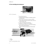
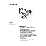
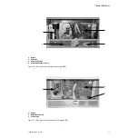
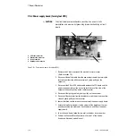
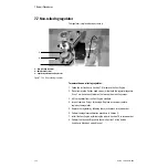
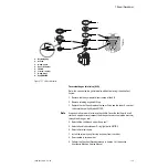
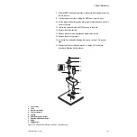
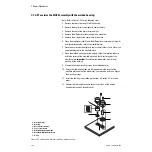
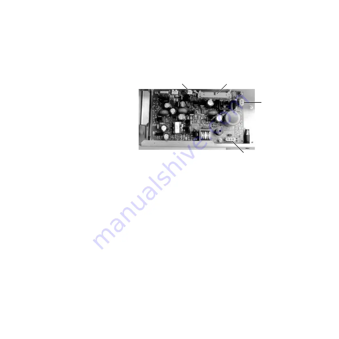
Figure 7-8 • Power supply board (for original CPU)
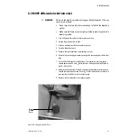
1. Remove the AC inlet module and the electrical enclosure cover
2. Disconnect the battery cable from the power supply board by pressing the
lock tabs on either side of the connector and gently pulling on the
connector.
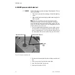
3. Disconnect the 50-pin CPU ribbon cable between the CPU board and the
power supply board by pulling out on the lock tabs on either side of the
connector and gently pulling on the cable connector.
4. Disconnect the lighting cable by gently pulling on the connector.
5. Disconnect the connector from the toroid by pressing the lock tabs on either
side and gently pulling on the connector.
6. Loosen the three captive screws at each corner of the power supply board.
7. Unlock the two Nylon retainers (on the corners of the board near the rear
panel) by bending their tabs away from the board, and lift out the power
supply board.
8. To install a new board, follow the removal instructions in reverse order.
9. Perform the Checkout Procedure found in Section 3 of the Aestiva
Anesthesia Machine Service Manual.
1
2
3
1. CPU cable connector
2. Battery cable connector
3. Toroid connector
4. Lighting cable connector
4
Summary of Contents for Aestiva 7900 SmartVent
Page 1: ...Aestiva 5 7900 Anesthesia Ventilator Technical Reference Manual ...
Page 44: ...Notes 2 28 05 04 1006 0453 000 ...
Page 82: ...Notes 4a 36 05 04 1006 0453 000 ...
Page 116: ...Notes 4b 34 05 04 1006 0453 000 ...
Page 150: ...Notes 5 34 05 04 1006 0453 000 ...
Page 158: ...Notes 6 8 05 04 1006 0453 000 ...
Page 182: ...Notes 7 24 05 04 1006 0453 000 ...
Page 202: ...Notes 8 20 05 04 1006 0453 000 ...
Page 203: ......

