2 Theory of Operation
1006-0453-000 05/04
2-7
2.3.3 Sensor Interface
Board (SIB)
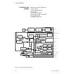
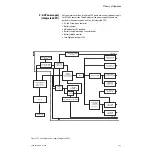
A Sensor Interface Board (SIB) serves as the interface between the ventilator
CPU board and the breathing circuit sensors.
The SIB processes signals from the:
• Inspiratory and expiratory flow transducers
• O
2
sensor
• Auxiliary Common Gas Outlet (ACGO) switch (optional)
• Module ID board
• Canister release switch
• Absorber CO
2
Bypass switch
• Bag/Vent switch
• Control panel switch
• Drive Pressure Limit (DPL) switch
• Manifold pressure transducer
• Patient airway pressure transducer
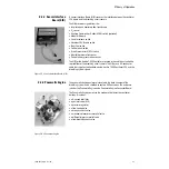
The SIB for the Aestiva 7900 Ventilator is located in the cable duct under the
rear subfloor of the breathing circuit chassis. The SIB uses a 50-conductor
cable that supplies the link between the Aestiva 7900 Ventilator CPU and the
breathing system signals.
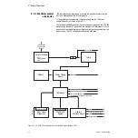
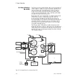
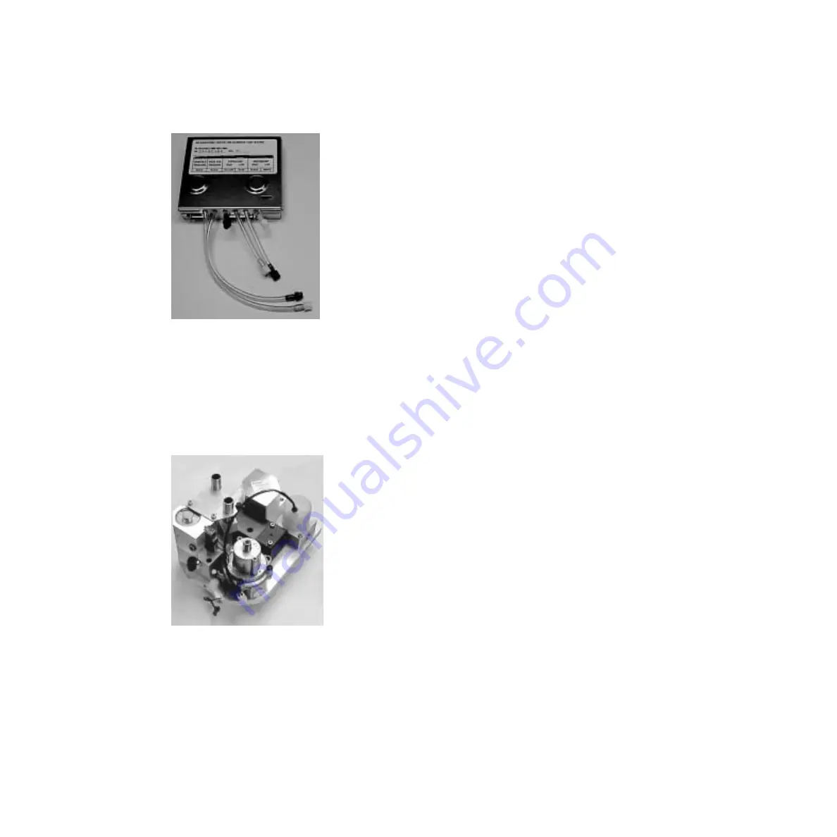
Figure 2-5 • Sensor Interface Board (SIB)
2.3.4 Pneumatic Engine
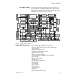
The pneumatic engine enclosure is located in the back chamber of the
breathing system and is shielded to contain EMI emissions. The enclosure
includes the Pneumatic Engine and a Pneumatic Engine Connector Board.
The Pneumatic Engine comprises the hardware that drives the ventilator
bellows. It includes:
• a 5-micron inlet filter
• a gas inlet valve (GIV)
• a pressure regulator
• a flow control valve
• a drive gas check valve
• a mechanical over-pressure relief valve
• a differential pressure relief valve
• a free-breathing check valve
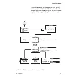
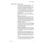
Figure 2-6 • Pneumatic Engine
Summary of Contents for Aestiva 7900 SmartVent
Page 1: ...Aestiva 5 7900 Anesthesia Ventilator Technical Reference Manual ...
Page 44: ...Notes 2 28 05 04 1006 0453 000 ...
Page 82: ...Notes 4a 36 05 04 1006 0453 000 ...
Page 116: ...Notes 4b 34 05 04 1006 0453 000 ...
Page 150: ...Notes 5 34 05 04 1006 0453 000 ...
Page 158: ...Notes 6 8 05 04 1006 0453 000 ...
Page 182: ...Notes 7 24 05 04 1006 0453 000 ...
Page 202: ...Notes 8 20 05 04 1006 0453 000 ...
Page 203: ......


