18
Installation
Pressure relief valves are sized to protect the system. Never change the pressure setting or
tamper with the valve. Only the valve manufacturer and their authorized representatives are
allowed to make such changes.
Pressure relief valves are used to protect system integrity in accordance with
safety standards. Failure to provide properly sized valves will result in death or
serious injury.
Pressure relief valves are installed prior to any potential blockage point such as shutoff
valves, heat exchangers and discharge silencers. Ideally, the valve should be threaded
directly into the pressure point it is sensing, not connected with tubing or pipe. Always
direct discharge from relief valves to a safe area away from personnel.
4.4 FLUID LEVEL INSPECTION
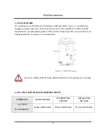
Inspect the fluid level when the compressor is in shut down mode. Fluid level is indicated
on the reservoir sight glass (see figure 3-1). The maximum fluid level is at the top red-mark.
Add fluid until the top red-mark is reached.
4.5 ELECTRICAL
Before installation, the electrical supply should be checked for adequate wire size and
capacity. User must comply with national & local electrical codes. The codes specify the
surrounding clearance requirement for the electrical panel. Wiring work should be
undertaken only by a qualified electrician in compliance with OSHA, national or local
electrical code. GC compressor provides wiring diagrams for user reference. Refer to the
electrical control schematic in the parts manual for wiring diagrams. Genuine fused
disconnect switch or circuit breaker should be purchased from the manufacturer. Any
unreasonable voltage imbalance (5%) between phases must be eliminated and low voltage
problems must be corrected to prevent excessive current draw. Air compressors must be
grounded in accordance with applicable codes, regulations and requirement.
Installation
Summary of Contents for CSST13020
Page 1: ...SCREW AIR COMPRESSOR CSST13020 Instruction Manual Release August 2018 ...
Page 2: ......
Page 47: ...4 5 Servicing ...

