USER’S MANUAL
15
Chapter 4 INSTALLAION
To avoid failure of machine safety equipment, can insert a wood in the middle part of
joint-pole.
Prohibit working beneath the lift when hydraulic system is not completely equipped
with hydraulic oil and take the action of up and down operations.
-When moving the lift platform, adjust the space between two platforms make sure that the
two platforms are parallel.
LINE CONNECTION
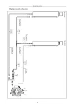
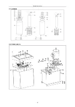
Connect the electrical and oil pipes according to “the electrical diagram” and “oil pipe
connection diagram”.
Only after connecting the hydraulic system can connect the air loop, can not damage
oil pipe, wires, and air pipe.
In the process of connecting oil pipe and air pipe, pay particularly attention to the
protection of pipe tie-in to prevent abnormal thing from entering oil loop and air loop,
then damaging hydraulic system.
ELECRICAL CIRCUIT CONNECTION
:
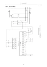
Follow the stated line- pathway and line-number of “the electrical diagram” to connect
electrical circuit.
Only skilled person is allowed to perform the operations.
-Open the control box front cover
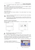
-Connection of power supply: the 400V three-phase and five-line connection wires
(
3×2.5mm
2
+
2×1.5 mm
2
cable wire) for power supply are connected to control box L1,L2,L3,N
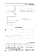
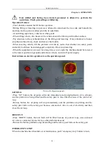
and entering-wire terminal. The PE ground wire is connected under the bolt marked ground
firstly (Picture 15) and then connected under the bolt marked ground of two platforms.
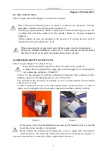
-If the lift is operated at 230V three-phase, change the connection on the transformer and
motor. (Picture 1
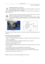
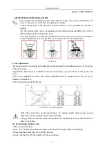
-Connection of up limit switch (picture 17):
This For detail connection, please see electrical drawing.
Picture15
Picture 16
Picture 17 (up limit switch)


