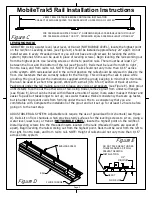
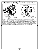
background image


Figure F

DECKING

DECKING

DECKING

DECKING

Figure G

#10 x 1" SELF

TAPPING SCREW

SPLICE PLATE

RAIL

DECK END TRIM

DECKING

#10 x 3/4" PARTICLE

BOARD SCREW

FLANGE OF

END TRIM

Page 4

MobileTrak5 Decking Installation Instructions

INSTALLING DECKING

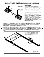
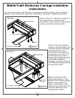
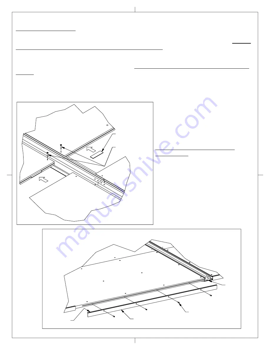
Check to make sure that the decking has 1/4-20 T-nuts installed on the bottom. Use the decking 

layout sheet supplied with each job as a guide. Install the decking sections from left to right, making 

sure to install (3) splice plates between each section of decking (see Figure F). After all sections of 

decking are laid out, it must be secured to the rails. To secure: Drill pilot holes through the pre-drilled 

holes in the decking into the flange of the rail (space approximately 12" apart). Then use #10 x 1" 

long self tapping screws to secure decking to rails. Make sure that rails do not move while attaching 

decking (see Figure C. To make decking more rigid and eliminate "bounce", install 1/4-20 x 1 1/4" long

leveling screws through the T-nuts in decking until they contact floor and level with a 2' bubble level 

(NOTE: try not to put weight on the decking while this is being done). Repeat for the remaining 

decking sections. (NOTE: If the system is equipped with side ramps, skip to the section on installing 

side ramps before attaching decking to system).

INSTALLING DECK END TRIM 

(OPTIONAL)

Deck end trim is used in some cases to 

cover the exposed end of a system (see 

Figure G). Deck end trim is supplied in 

standard sizes. In most cases these pieces 

need to be cut in the field to fit. Deck end 

trim is to cover decking only. Do not cover 

the ends of the rails. After measuring and 

cutting pieces to length, attach to decking 

with the flange sitting on top of the 

decking with #10 x 3/4" pan head Phillips 

screws.

Summary of Contents for MobileTrak5

Page 1: ...S BEFORE STARTING INST0111 REV1 NFW 5 8 06 Tools Required for Assembly 7 16 1 2 Wrench Phillips Head Screwdriver Rubber Mallet 1 8 5 32 1 4 Allen Wrenches Mortar Trowel Optional Tape Measure Not Shown but required Transit Laser Level or Water Level Electric Drill 2 Bubble Level 9 Bubble Level Optional Equipment Mortar Mixing Equipment ...

Page 2: ...ond rail with all tags to the right then alternate each additional rail Rail sections are connected together with 1 4 steel pins and are secured with 4 5 16 18 x 1 4 long set screws see Figure A Make sure rail sections are butted tightly together before tightening set screws 2 Position all of the rail sections on the floor in the approximate location where they will be used Use decking sections to...

Page 3: ...6 foot section of track at a time Pack grout under the rail making sure not to leave any voids or air pockets see Figure E Pack grout until it starts to come out the other side of rail Using trowel remove grout from under rail flanges see Figure E Grout can be mixed with different amounts of water more water makes it thinner and easier to pack but takes longer to set up less water makes a thicker ...

Page 4: ...o secure decking to rails Make sure that rails do not move while attaching decking see Figure C To make decking more rigid and eliminate bounce install 1 4 20 x 1 1 4 long leveling screws through the T nuts in decking until they contact floor and level with a 2 bubble level NOTE try not to put weight on the decking while this is being done Repeat for the remaining decking sections NOTE If the syst...

Page 5: ...stationary units INSTALLING A D A COMPLIANT RAMP OPTIONAL Attach the metal ramp section to the wood ramp section using 10 x 3 4 particle board screws see Figure J Lay the assembled section of the ramp on to the front most rail and attach using 10 x 1 1 4 flat head Phillips Tek screws Repeat step for additional sections of ramp Be sure to use deck splice places between ramp sections INSTALLING SIDE...

Page 6: ...T FILLER RAIL SET SCREWS FLANGED WHEEL SET SCREWS RAIL NO FLANGE WHEEL TALL FILLER Tall track filler is used in all gaps except where the flanged part of a wheel is located see Figure L In cases where the flanged part of a wheel sits a short track filler is used see Figure M ...

Page 7: ...THIS PAGE INTENTIONALLY LEFT BLANK Page 7 MobileTrak5 Installation Instructions ...

Page 8: ...may be shipped already attached to one end of the carriage using 5 16 18 x 3 4 hex head bolts and Nylock nuts Do not tighten at this time On manual and stationary slide next section on to connector and bolt into position using 5 16 18 x 3 4 hex head bolts and Nylock nuts see Figure N Tighten all screws On Mechanical Assist carriages slide next section onto connector assembly To connect drive shaft...

Page 9: ... 5 16 18 NYLOCK NUT 5 16 18 x 3 4 BOLT Measure location of shelving uprights on shelving that is being used see Figure Q Locate holes in carriage that will place the shelving supports under the uprights of the shelving being used Insert 5 16 18 x 3 4 hex head bolts and 5 16 Nylock nuts in carriage and tighten most of the way see Figure P Slide shelf supports over bolts and finish tightening NOTE L...

Page 10: ...ly With carriages on track slide one anti tip bracket under carriage making sure that anti tip bracket stays hooked under anti tip channel Attach bracket to wheel channel flange on underside of carriage using two 5 16 18 x 1 2 hex head bolts lock washers and flat washers see Figure R Tighten screws making sure that bracket does not bind or scrape against anti tip channel see Figure S Repeat for re...

Page 11: ...ssmember on the underside of the stationary carriage four glides per crossmember Method 2 Figure U Stationary carriage is mounted directly to top of decking Attach two stationary mounting brackets to each crossmember on the stationary carriage with two 5 16 18 x 1 2 hex head bolts per mounting bracket After installing mounting brackets attach stationary carriage s to decking using 10 x 3 4 Phillip...

Page 12: ...tionary carriage 3 System has stationary carriages but they are not secured to floor or top of decking ANGLE END STOP BRACKET Using two 5 16 18 x 3 4 allen button head screws fasten end stop on top of rail see Figure V Attach rubber bumper to bracket with 1 4 20 x 3 8 pan head Phillips screw ALUMINUM END STOP BRACKET Using two 5 16 18 allen cap screws attach end stop bracketon top of rail with rub...

Page 13: ...R ARE TIGHT CARRIAGE 10 x 1 2 PAN HEAD PHILLIPS TEK SCREW CARRIAGE COVER PLATES INSTALLING CARRIAGE COVER PLATES OPTIONAL Typically a carriage cover plate is used where the shelving is not as large as the carriage it s attached to Center the carriage cover plate on the appropriate carriage and secure using 10 x 1 2 long pan head Phillips Tek screws CHAIN ...

Page 14: ...te the possibility of shelving falling over or off the carriage USE CAUTION when drilling or screwing into carriage Drilling or screwing into carriage wheels will cause carriages to be difficult if not impossible to move When racks or shelving units are mounted back to back on carriages it is required that they be bolted together back to back and side to side using hardware supplied by installer ...

Page 15: ...ead bolts Place woodruff key in drive shaft Slide sprocket over drive shaft aligning woodruff key with sprocket Slide sprocket so that front is 1 4 from the front of the driveshaft see Figure 1A Place blue locktite on 1 4 20 set screw and tighten Route chain on drive tower as shown in Figure 1B Connect ends of chain together using master link Adjust chain tensioner so that chain is tight Do not pu...

Page 16: ...ight side of the mounting bracket see Figure 1C Turn T handle so that the lock cam is in the vertical position which will allow it to slide in the lock bar CHAIN LOCK BAR MOUNTING BRACKET If using drive tower cover place cover over drive tower Secure in place using 4 8 x 3 8 Tek screws see Figure 1D Check to make sure that the T handle engages lock bar by turning handle to locked position and ensu...

Page 17: ...8 x 1 2 Tek screws into top of shelving on carriage through holes in top spacer bracket see Figure 1F Attach female end panel clips to uprights using 2 8 x 1 2 sheet metal screws per clip see Detail 1G The clip opening should be facing away from shelving If using 3 piece end panels clips will be used on all sets of holes in uprights If using a 1 piece end panel clips will be used in bottom holes t...

Page 18: ...MobileTrak5 Installation Instructions THIS PAGE INTENTIONALLY LEFT BLANK Page 18 ...

Page 19: ...E END PANEL 8 x 1 2 SCREW END PANEL CLIP MALE HALF Install male end panel clips to end panels using 2 8 x 1 2 sheet metal screws per clip Place flat side of male clip towards outside of end panel see Figure 1J Install 6 clips per one piece panel see Figure 1H Install 4 clips per panel on 3 piece end panels making 12 clips in total see Figure 1I PLACE FLAT PORTION OF CLIP TOWARDS SIDE OF PANEL END ...

Page 20: ... to wood panel with 8 32 x 7 8 machine screw Attach to steel end panel with 8 32 x 3 8 machine screws Screw first 3 8 jam nut on to T handle Place lock cam on handle shaft as shown in Figure 1J Finger tighten second jam nut onto handle shaft Distance cam 1 8 from end of handle shaft see Figure 1L Fully tighten jam nuts INSTALLING END PANELS If using steel end panels attach steel panel spacers to d...

Page 21: ...E FLAT WASHER 5 16 18 x 5 8 HEX FLANGE BOLT HUB COVER 3 SPOKE SHOWN OTHERS ARE SIMILAR Align 3 crank shaft hub holes with 3 holes in crank Install 1 4 20 x 1 2 hex bolts with 1 4 lock washers through crank into crank shaft hub see Figure 1M Place handle knob into crank and tighten with M10 x 1 5 nuts Place key in slot on crank shaft Slide crank assembly onto crank shaft aligning hub slot with key ...

Page 22: ...MobilTrak5 Completed Mechanical End Panel Page 22 3 PIECE SHOWN 1 PIECE SIMILAR ...

Page 23: ...Page 23 MobileTrak5 Installation Instructions THIS PAGE INTENTIONALLY LEFT BLANK ...

Page 24: ...r pull handle have the threaded inserts T nuts in them see Figure 1T Place end panel against shelving being sure bottom of end panel is flush with bottom of carriage With someone holding panel in place drill through shelving and into the back side of the laminated panel see Figures 1U 1V DO NOT DRILL COMPLETELY THROUGH LAMINATED END PANEL Use 8 x 1 2 wood screws to attach panel to shelving End pan...

Page 25: ... Tek screws see Figure 1X NOTE Channels are manufactured 1 8 shorter than the width of the shelving it s covering ex 36 wide shelving will have 35 7 8 long channels so space channels accordingly Attach the side bracket to one of the rear panels using four 8 x 1 2 wood screws see Figure 1Y Position the bracket on the edge of the panel and center vertically On the same panel attach two upper bracket...

Page 26: ... THINSTAK If the the system is equipped with Datum ThinStak style shelving the top cover will have knockouts in it to align with the holes in the upper brackets see Figure 2A If any shelving other than Datum Thinstak shelving is being used holes will need to be drilled into the top of the shelving Four 1 4 20 x 1 2 pan head Phillips screws and flanged nuts are supplied to attach upper brackets to ...

Page 27: ...biscuit joint with the hole in the side of the panel see Figure 2B Attach another set of upper brackets to the rear panel If the system is equipped with Datum ThinStak style shelving the top cover will have knockouts in it to align with the holes in upper brackets If any shelving other than Datum ThinStak shelving is being used holes will need to be drilled into the top of shelving 1 4 20 x 1 2 pa...

Page 28: ...Page 28 MobileTrak5 Installation Instructions If you need assembly assistance please contact Customer Service at 1 866 217 0330 Monday through Friday 8 00 A M 5 00 P M E S T ...

Reviews: