background image


26 


XV.


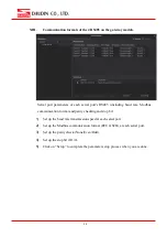
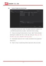
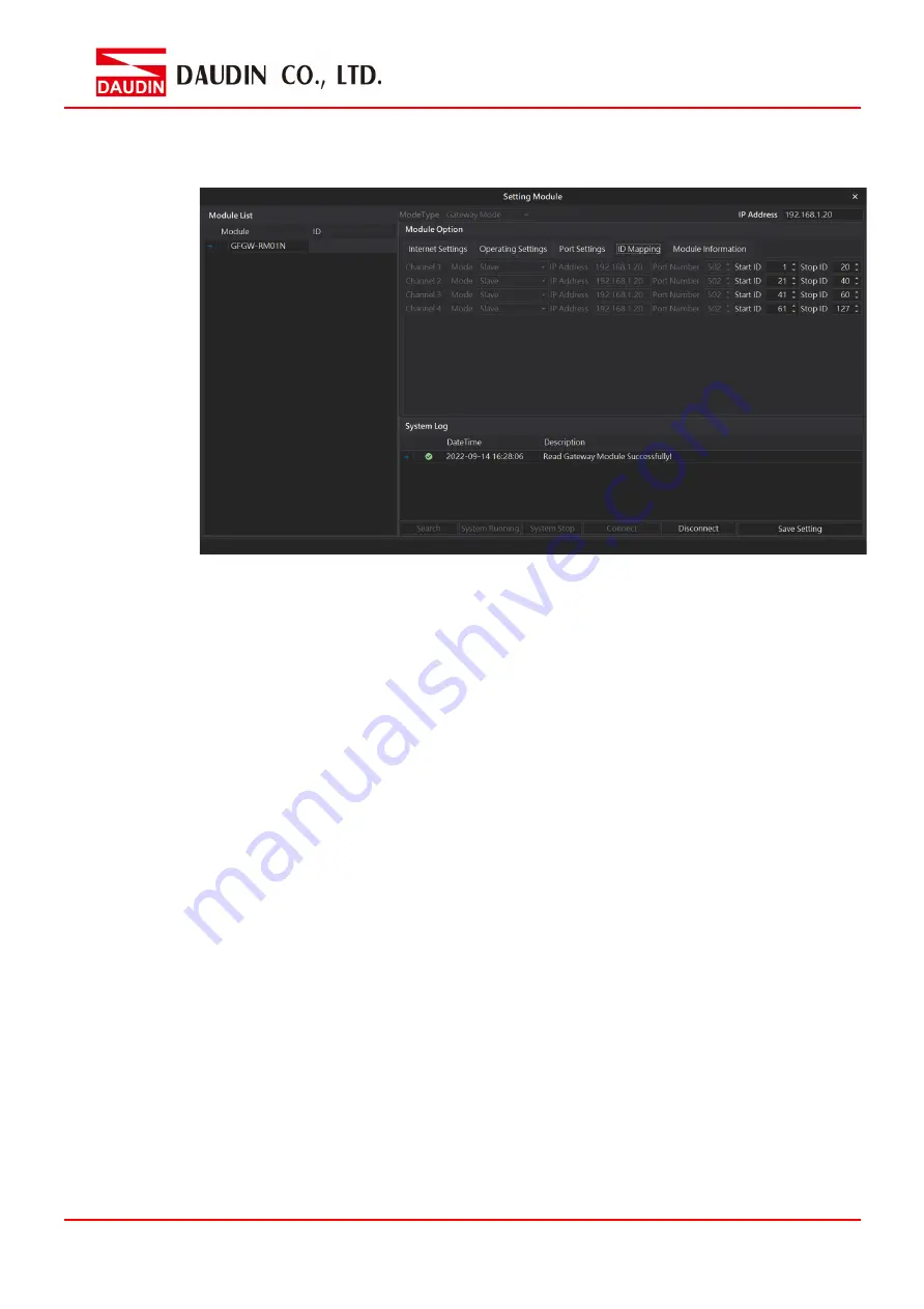
Gateway Module ID mapping 


ID mapping parameters include: mapping IP of the master module in the operation 

mode and the mapping ID range for the slave module.   

1) 

In the “master” module’s operation mode, set up the corresponding master’s IP 

address. 

2) 

In the “slave”  module’s operation mode, set up the corresponding slave’s ID 

range (decimal system) 

3) 

Click on “Setup” to complete the parameter setup process when you are done. 


Summary of Contents for iO-GridM GFGW-RM02N

Page 1: ...iO GRID M Gateway Module User Manual 2211TW V3 0 0...

Page 2: ...ateway Module Dimensions 7 3 2 Gateway Module Panel Information 8 4 Module Installation Disassembly 11 4 1 Installation 11 4 2 Removal 12 5 iO GRID M Series Introduction 13 5 1 iO GRID M Components 13...

Page 3: ...open industrial device for installation in a housing provided on site It is a standard Modbus gateway that converts between Modbus TCP and Modbus RTU ASCII protocols For TCP masters it supports up to...

Page 4: ...NSTALLATION THAT THE SAFETY OF ANY SYSTEM INCORPORATING THE EQUIPMENT IS THE RESPONSIBILITY OF THE ASSEMBLER OF THE SYSTEM L INSTALLATION DE TOUT SYST ME INT GRANT CET QUIPEMENT EST LA RESPONSABILIT D...

Page 5: ...rface RS485 push in contact Communication Protocol Modbus TCP RTU General Specification Dimension W D H 20 x 100 x 97mm Weight 84g Ambient temperature operation 10 60 C Storage Temperature 25 C 85 C P...

Page 6: ...ication Interface RS485 via Dinkle Bus Communication Protocol Modbus TCP RTU General Specification Dimension W D H 20 x 100 x 97mm Weight 79 Ambient Temperature operation 10 60 C Storage temperature 2...

Page 7: ...7 3 Gateway Module Information 3 1 Gateway Module Dimensions I GFGW RM01N II GWGW RM02N Unit mm Unit mm...

Page 8: ...ng Off Power off RST Green Reset Indicator Blinking Reset to default setting 3 seconds after initiating IP reset ERR Red Anomaly Indicator On System anomaly Off Status normal LED indicator Ethernet re...

Page 9: ...rt A of the first RS485 2 Serial port B of the first RS485 3 Serial port A of the second RS485 4 Serial port B of the second RS485 5 Serial port A of the third RS485 6 Serial port B of the third RS485...

Page 10: ...set indicator Blinking Reset to default setting 3 seconds after initiating IP reset ERR Red Anomaly indicator On System anomaly Off Status normal RS485 communication indicator definitions RS485 RS485...

Page 11: ...e to the arrow on the DIN rail II Press the module down and the metal clamp will slide thanks to its spring mechanism and grab on the other side of the DIN rail Continue to push down until the metal c...

Page 12: ...12 4 2 Removal I Use a screwdriver to pull the metal hook sideways and detach the module from the DIN rail II Remove all modules from the DIN rail in reverse order of installation...

Page 13: ...us TCP Please choose products and factory controllers to figure your system based on your communication protocol 5 1 iO GRID M Components I DINKLE Bus Rail 1 to 4 are defined for power supply and rail...

Page 14: ...GFGW RM02N Modbus TCP to Modbus RTU ASCII gateway module 1 Port III Control module The control module manages I O modules and sets up the configuration Provides external RS485 ports to connect to the...

Page 15: ...input module 0 10VDC GFAI RM20 4 channel analog input module 0 20mA GFAI RM21 4 channel analog input module 4 20mA GFAO RM10 4 channel analog output module 10VDC GFAO RM11 4 channel analog output modu...

Page 16: ...the following parameters 1 IP address subnet mask default gateway 2 Communication parameters of each serial port s RS485 including baud rate Modbus communication format and parity checking and stop bi...

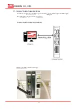
Page 17: ...n Setup Connect your gateway module to your computer via the Internet port and then open the i Designer program to set up gateway module parameters Gateway module connection illustration Gateway modul...

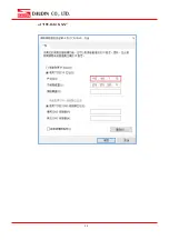
Page 18: ...he gateway module to your computer open Control Panel All Control Panel Items Network and Sharing Center and then click on Change adapter settings 2 Click on the Ethernet icon Properties and then clic...

Page 19: ...19 of 192 168 1 XXX...

Page 20: ...20 V Make sure that the module is powered and connected to the gateway module using an Ethernet cable VI Click to launch the software...

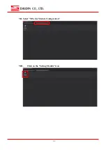
Page 21: ...21 VII Select M Series Module Configuration VIII Click on the Setting Module icon...

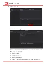
Page 22: ...22 IX Enter the Setting Module page for M series X Select the mode type based on the connected module...

Page 23: ...twork setting parameters include IP address subnet mask default gateway and MAC address non changeable 1 Set up the IP address 2 Set up the subnet mask 3 Set up the default gateway 4 Click on Setup to...

Page 24: ...Modbus communication format and parity checking and stop bit 1 Set up the baud rate transmission speed at each serial port 2 Set up the Modbus communication format RTU ASCII at each serial port 3 Set...

Page 25: ...settings 1 Choose each serial port s master and slave Choose master for the serial ports connecting the controller and slave for the other serial ports Simply put when TCP RTU choose slave when RTU TC...

Page 26: ...n mode and the mapping ID range for the slave module 1 In the master module s operation mode set up the corresponding master s IP address 2 In the slave module s operation mode set up the correspondin...

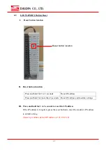
Page 27: ...ddress Press and hold for more than 3 seconds Reset IP address and module settings III Press and hold for 1 to 3 seconds to reset the IP address If the IP address is forgotten press the reset button t...

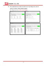
Page 28: ...28 IV Press and hold for more than 3 seconds to reset operating mode network settings serial port setting and ID mapping The image below is the module default settings...

Reviews: