D i d o H a r d w a r e M a n u a l
v . 1 . 0 . 5
6
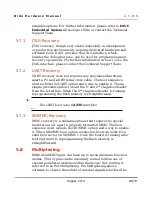
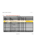
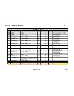
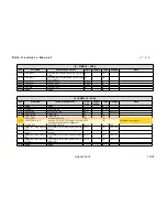
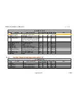
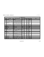
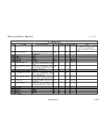
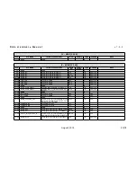
Pinout table
This chapter contains the pinout description of the DIDO
module, grouped in four tables (two – odd and even pins – for
each connector) that report the pin mapping of the two 140 pin
DIDO connectors.
Each row in the pinout tables contains the following
information:
Pin
Reference to the connector pin
Pin Name
Pin (signal) name on the DIDO connectors
Internal
Connections
Connections to the DIDO components:
CPU.<x> : pin connected to CPU pad named <x>
KEY.<x>: pin connected to the key switch controller
TSC.<x> : pin connected to the touchscreen
controller
EEPROM.<x> : pin connected to the EEPROM
CAN.<x> : pin connected to the CAN transceiver
PMIC.<x> : pin connected to the Power Manager IC
LAN.<x> : pin connected to the LAN PHY
USB.<x> : pin connected to the USB transceiver
SV.<x>: pin connected to voltage supervisor
MTR: pin connected to voltage monitors
Ball/pin #
Component ball/pin number connected to signal
Supply Group
Power Supply Group
Type
Pin type: I = Input, O = Output, D= Differential, Z =
High impedance, S = Supply voltage, G = Ground, A
= Analog signal
Voltage
I/O voltage
The
Internal connection
column reports the name of the
microprocessor signal, which in turn contains references to all
the peripheral functions that can be associated to that pin. For
example, the following pin name
CPU.VOUT[1]_B_CB_C[4]/EMAC[1]_MRXD[0]/VIN[1]A_D[1]/UA
RT4_RXD/GP3[1]
means that the pin can be used as:
●
VOUT[1]_B_CB_C[4]: Video output data, port 1, B/CB/C
color bit 4
August, 2014
30/78


